The 5D Manufacturing Methodology
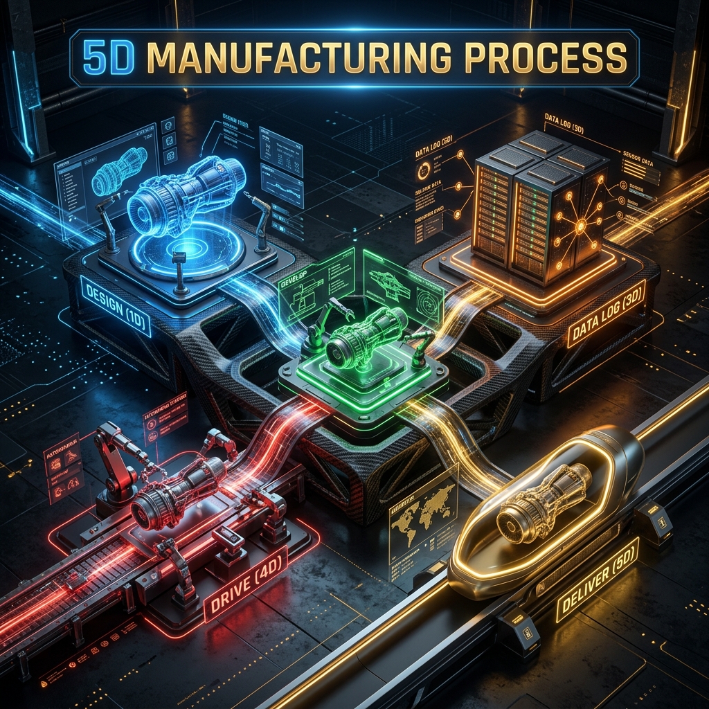
A comprehensive guide to scaling custom manufacturing using the 5D Framework: Design, Develop, Data Log, Drive, and Deliver.
Traditional manufacturing forces a frustrating compromise: the rigid consistency of mass production versus the unscalable precision of artisanal craftsmanship. For Predator Cycling, neither model was acceptable. We needed to build Olympic-caliber bicycles, perfectly fitted to individual athletes, with the reliability and speed of a factory.
The solution was not building better tools, but designing a better system. The 5D Manufacturing Methodology is a rigorous framework that transforms the factory floor into a software-defined ecosystem where data drives every decision — enabling Mass Customization at scale.
Table of contents
- Design: From Static Geometry to Parametric Intelligence
- Develop: Killing the Prototype via the Digital Twin
- Data Log: The Digital Birth Certificate
- Drive: Closing the Reality Gap
- Deliver: Validating the Engineering Promise
- Summary: A Blueprint for Distributed Industry
Design: From Static Geometry to Parametric Intelligence
The first “D” is Design. Unlike traditional approaches that produce static artifacts — a CAD drawing with fixed lengths requiring manual redrawing for every customer change — the 5D approach treats design as an engineering constraint problem.
The Shift to Constraint Logic
We rely heavily on Parametric Intelligence, primarily executed via Autodesk Fusion 360:
- The Model as an Equation: A bicycle frame is treated as a system of variables (e.g.,
Seat_Tube_Length,Head_Tube_Angle). - Digital Guardrails: We code hard logic into the model (e.g.,
IF Seat_Tube_Angle < 73 deg THEN Chain_Stay_Length MUST >= 405mm), ensuring every output is mechanically valid and safe. - Instant Regeneration: When customer biometric data is inputted, the model “regenerates” in seconds to produce a uniquely tailored, valid geometry ready for production.
Develop: Killing the Prototype via the Digital Twin
The “Develop” phase is dedicated to entirely eliminating the wasteful “Mold-Break-Iterate” R&D cycle. In physical prototyping, you build, test to failure, learn, and rebuild — a massive resource sink.
High-Fidelity Simulation
We replaced the physical build process with a stringent Digital Twin strategy before spending a single dollar on materials:
- Computational Fluid Dynamics (CFD): Using Ansys Fluent, we place a virtual bike and rider in a digital wind tunnel to iterate dozens of airfoil shapes per night.
- Finite Element Analysis (FEA): We simulate the composite layup schedule ply-by-ply, applying virtual sprinting wattages and pothole impacts to pinpoint stress fractures.
KEY INSIGHT: By the time we cut the first physical mold, we are already on Version 50 of the design. The physical product works the first time because the math proved it would.
Data Log: The Digital Birth Certificate
In a “Smart Factory,” the physical product is only half the deliverable; the other half is the Data. We assign every manufactured component a Global Unique Identifier (GUID).
Building the Biographical Record
As the part moves through the factory, it accumulates a permanent digital biography:
- Material Traceability: Batch numbers, expiration dates, and ambient “out-time” for pre-preg carbon.
- Process Telemetry: Autoclave cure cycles including temperature ramp rates, vacuum pressure, and peak soak logs.
- Human Factors: Records of which technician laid up the part and who performed each 3-stage QC check.
If a frame fails years later, we pull the GUID to see exactly what happened during its creation — enabling closed-loop error prevention for all future runs.
Drive: Closing the Reality Gap
Engineering theory is useless without real-world validation. The “Drive” phase focuses on empirical testing in the field to confirm our desktop math.
The Validation Loop
- The Instrumented Mule: We equip test bikes with strain gauges, accelerometers, and power meters to capture real-time, high-frequency vibration and load data.
- Correlation Analysis: We compare real-world deflection with our FEA predictions (tolerance: 0.1mm).
- The Feedback Loop: If there is any delta between simulation and reality, we immediately update our simulation kernels — ensuring the system continually learns and adapts.
Deliver: Validating the Engineering Promise
The final “D” is Deliver. In traditional custom businesses, delivery is often an afterthought. In the 5D Methodology, it is the final, tangible execution of our engineering promise.
By integrating our logistics system directly with our manufacturing data:
- A “Hard Card” for the Owner: A dense technical spec sheet listing the exact geometry and build parameters of their unique machine.
- Live Progress Transparency: Customers receive granular tracking, seeing exactly which “D” their bespoke build is currently in.
- Traceable Excellence: We deliver an unboxing experience that perfectly reflects the cutting-edge engineering rigor inside the box.
Summary: A Blueprint for Distributed Industry
The 5D Manufacturing Methodology is not just a bicycle fabrication tool — it is a blueprint for the future of Distributed, High-Reliability Manufacturing. Whether applied to prosthetic limbs, custom drones, or aerospace components, the core principles remain constant:
- Parametrize the design to automate complex choices.
- Simulate the reality to kill the prototype phase.
- Log the creation to ensure total traceability.
- Validate the performance to close the feedback loop.
- Execute the logistics to thoroughly deliver the promise.
Q&A
Q: How does Mass Customization differ from simply offering standard variants? A: Unlike standard variations (small/medium/large), mass customization allows for an infinite matrix of bespoke geometrical changes per customer, all while retaining the efficiency of a fixed-size product run.
Q: Can the 5D Methodology be scaled to smaller operations? A: Absolutely. While tools like Fusion 360 and Ansys Fluent represent the highest tier, the underlying philosophy — parameterizing design, avoiding physical prototyping through math, and logging structural data — can be implemented at any scale.
Related Context
For more on how this methodology is applied in practice, see the Predator Cycling Case Study.