Framing the Future: Custom Cycling Design in Fusion 360
How we bridged custom carbon fiber frame modeling, T-Spline geometries, and CAM workflows in a single Autodesk Fusion 360 environment.
Bicycle frame design has long been constrained by traditional manufacturing limits. Custom carbon fiber fabrication traditionally required disjointed toolsets: one application for freeform industrial design, another for structural math, and a separate package for generating CNC toolpaths.
By unifying our entire product development cycle in Autodesk Fusion 360, we collapsed these functional silos. This post details how we leveraged T-Splines, parametric constraints, and integrated CAM to bring a custom carbon track frame from sketch to physical prototype.
Table of contents
- The Fragmentation of Custom Composites
- Unifying Industrial Design and CNC Machining
- Bridging CAD and CAM in the Workshop
- Summary: The Integrated Manufacturing Pipeline
The Fragmentation of Custom Composites
Custom carbon manufacturing is inherently complex. Standard CAD software handles rigid mechanical assemblies well, but fails when designing organic, aerodynamic tube shapes that must transition smoothly at critical junctions like the bottom bracket.
Historically, designers used separate surfacing applications to sculpt these organic forms. However, these surfaced models were “dumb” geometries that could not easily be modified parametrically. If a frame size or rider geometry changed by 5mm, the entire model had to be manually rebuilt from scratch.
KEY TAKEAWAY: The lack of integration between organic shape modeling and parametric math forces engineering teams to waste weeks rebuilding CAD files for every minor revision.
Unifying Industrial Design and CNC Machining
In our Autodesk University 2018 talk, we demonstrated how Fusion 360 solves this fragmentation. By combining T-Spline modeling with parametric controls, we created a flexible design model that is both highly organic and mathematically modifiable.
The Parametric Surfacing Workflow
- T-Spline Sculpting: We sculpted the aerodynamic junctions of the frame tubes using subdivision modeling, ensuring clean transitions.
- Parametric Constraints: We linked the endpoints of these surfaces to parametric dimensions (e.g., top tube length, head angle), allowing automatic sizing adjustments.
- Volumetric Solid Conversion: We converted these T-Splines into solid bodies to compute volumetric properties, shell thickness, and internal mold spaces.
Bridging CAD and CAM in the Workshop
Once the custom frame geometry is locked, the next bottleneck is generating the toolpaths for our multi-axis CNC machines to cut the tooling molds. Because Fusion 360 integrates CAD and CAM in a single environment, any design change propagates to the toolpaths instantly.
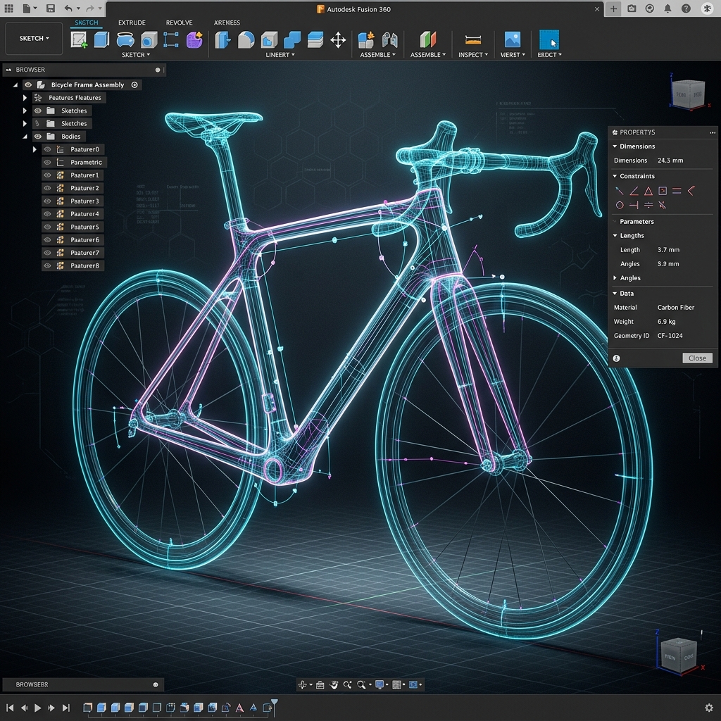
Figure 1: High-fidelity T-Spline modeling of a custom carbon track frame.
This integration eliminates the risk of exporting outdated file versions to the machine shop. We could simulate toolpaths, check for tool collisions, and post-process G-code directly in the same workspace where we designed the tubes.
Summary: The Integrated Manufacturing Pipeline
By removing file translations between design, engineering, and machining, we shortened custom frame R&D times significantly.
Key takeaways:
- T-Splines solve organic junctions: Combining subdivision surfaces with mechanical parametric constraints enables rapid scaling.
- Integrated CAD/CAM prevents errors: Eliminating the file export step ensures that the CNC machine cuts the exact geometry validated in the CAD model.
- Direct feedback loops: Machine shop tool constraints can be immediately adjusted in the core design file, eliminating rework.
Q&A
Q: How do you handle frame sizing updates with T-Splines? A: We anchor the control points of the T-Spline surfaces to a parametric skeleton line. When we adjust parameters like stack and reach, the T-Spline body conforms to the new points automatically.
Q: Did you cut the carbon fiber directly on the CNC? A: No, the CNC is used to machine the high-precision aluminum or high-density tooling molds. The carbon fiber sheets are then hand-laid into these molds and cured under high pressure.