High-Throughput Automation: Conveyance Kinematics, Real-Time Telemetry, and Agentic Controls
How conveyor accel/decel physics, optical timing registration, digital twins, and real-time unified datasets pave the way for agentic industrial operations.
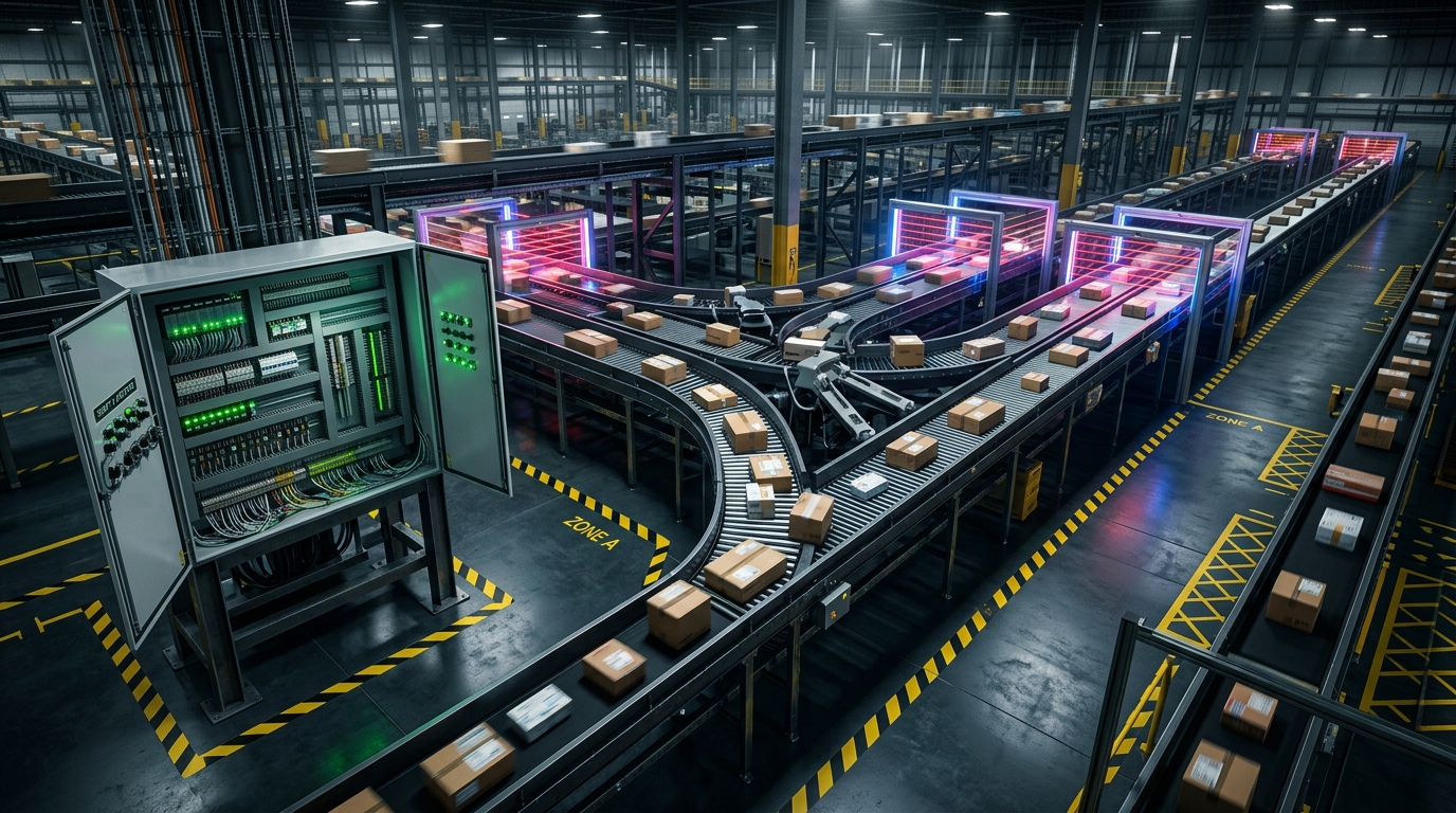
When you step inside a million-square-foot automated distribution facility, you are not looking at a warehouse.
You are looking at a massive, distributed physical computer running on gravity, momentum, and friction.
The conveyor belts are the physical data buses. The optical scan tunnels are the network interfaces. The packages—ranging from a 2-ounce polybag to a 45-pound corrugated carton—are discrete packets of data moving through space at 10 feet per second.
If software crashes on the web, a user refreshes their browser. If your controls logic experiences a 50-millisecond timing jitter on a high-speed linear sorter, several tons of freight violently concertina into a structural steel jam.
Having engineered automation systems, material handling controls, and robotics deployments across mega-scale facilities, the most compelling challenges are rarely about buying faster hardware. They are about understanding conveyance kinematics, mastering deterministic timing registration, leveraging digital twins, and structuring real-time unified datasets that transform passive industrial floors into platforms ready for agentic workflows.
Here is how we deconstruct automation from the physical mechanics of belt acceleration to the future of autonomous factory orchestration.
The Physics of Flow: Accel, Decel, and Package Inertia
Most material handling bottlenecks are created long before a package hits a diverter shoe. They start on the acceleration and deceleration belts of the conveyor beds.
A Variable Frequency Drive (VFD) controls the ramp rate of a 3-phase induction motor driving a rubberized conveyor belt. If you program a linear acceleration ramp (), the instantaneous jerk () spikes at the start and end of the ramp.
Linear Acceleration vs. S-Curve Motion Profiling:

Linear Ramp:
Velocity:    /─────────
Jerk:       ▲          ▲   <-- Sharp jerk spikes cause package slippage
            │          │

S-Curve Ramp:
Velocity:   ╭─────────╮
Jerk:       ┌┐        ┌┐   <-- Smooth derivative transitions preserve static friction
            └┘        └┘
When a belt experiences sudden jerk:
- High-friction items (corrugated kraft boxes) grip the belt and accelerate instantly.
- Low-friction items (smooth polybags, shrink-wrapped trays) break static friction () and slip into dynamic friction ().
The moment a package slips on the belt, the supervisory tracking system loses registration. The Programmable Logic Controller (PLC) believes the package is at position based on encoder pulse counts, but the package physically lags at .
By transitioning all VFD profiles from linear ramps to mathematical S-curve profiles (jerk-limited motion), we eliminate relative slip between belt and payload. Packages maintain their physical registration through aggressive high-speed transfers without tumbling or drifting out of their designated timing windows.
Optical Registration: Turning Microseconds into Millimeters
To route thousands of packages an hour, you must register physical objects into digital memory with absolute precision. This is governed by optical photo-eye sensors, rotary pulse encoders, and deterministic cyclic scan loops.
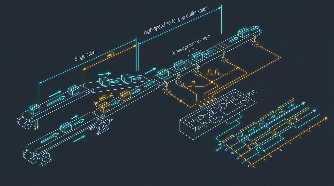
Leading Edge vs. Trailing Edge
A standard photo-eye detects light occlusion. But a naive control program that only checks if an input is “HIGH” or “LOW” will fail on irregularly shaped parcels (e.g., mailer bags with loose flaps or unsealed tape).
High-speed conveyance demands edge-interrupt processing:
- Leading-Edge Timestamping: Capturing the exact encoder tick () the instant the light beam breaks. This registers the package’s physical arrival down to a fraction of a millimeter.
- Debounce Windows: Filtering out fluttering polybag flaps by enforcing a minimum time-over-beam threshold ().
- Trailing-Edge Calculation: Logging the exit tick () to calculate real-world physical package length:
By reading live dynamic length from the optical sensors rather than trusting static manifest data from the cloud, the PLC can dynamically adjust downstream gapping belts on the fly.
Debottlenecking the Sorter: The Math of Dynamic Pitch
In high-speed distribution, linear sortation capacity is frequently throttled by conservative, static safety buffers.
OEM control systems often program fixed time windows between parcels. For example, inserting a 600-millisecond gap between every single item regardless of size. On paper, it is safe; on the facility floor, it leaves miles of empty conveyor belt during peak volume.
Moving to Dynamic Velocity Gapping
By taking dynamic length from optical registration and weight from in-line dynamic check-weighers, we can calculate the minimum safe gap () required for clean diverter shoe travel:
Where:
- is the mechanical clearance needed for the diverter pin switch.
- represents the kinetic momentum of the incoming parcel.
- represents the frictional braking resistance of the conveyor bed.
Small, rigid parcels can be safely nested with just 8 inches of gap. Heavy, slick boxes are granted larger deceleration margins.
Upstream Pre-Singulation
Coupling dynamic gapping with upstream pre-singulation transforms the bottleneck. By staggering belt speeds across parallel feeder lanes, bulk flows naturally elongate into a longitudinal single-file stream before ever entering the singulation bottleneck.
This controls rewrite directly unlocks 15% to 20% gains in total package throughput, boosting successful diversion rates while completely eliminating the multi-million-dollar capital expense of installing redundant conveyor steel.
Digital Twins: Simulating the Physical Boundary
Testing new controls logic on an active, live production conveyor line is high-stakes engineering. If your ladder logic has an edge-case race condition, you discover it when three parcels arrive simultaneously at Divert Chute 14 and crash the line during peak shift.
This is where Digital Twins and true physics analytics become an indispensable engineering discipline.
Digital Twin Closed-Loop Integration:
┌─────────────────────────┐          ┌─────────────────────────┐
│ Physics Simulation Env  │  ◄─────► │  Live PLC Emulation     │
│ (USD / Kinematic Meshes)│          │  (Real Ladder Scan Loop)│
└────────────┬────────────┘          └────────────┬────────────┘
             │                                    │
             ▼                                    ▼
┌──────────────────────────────────────────────────────────────┐
│ Stress-Testing Edge Cases:                                   │
│ - Chute full sensor debounce failure                         │
│ - Instantaneous VFD motor thermal trip                       │
│ - High-inertia package slip during emergency brake stop      │
└──────────────────────────────────────────────────────────────┘
A digital twin is not a 3D visual rendering for marketing; it is a mathematical and kinematic emulation of the physical system:
- Friction and Mass Emulation: Accurately modeling coefficient of friction variations when wet parcels travel on cold belts.
- Actuator Latency Modeling: Simulating the 35 ms pneumatic solenoid lag and 20 ms mechanical pin travel time under real-world air pressure drops.
- Virtual Commissioning: Running the exact compiled PLC ladder logic against virtual sensors in an NVIDIA Omniverse or specialized physics simulation environment.
By simulating thousands of hours of high-volume freight surges virtually, edge cases are falsified and solved on desktop workstations before an electrician touches a single terminal block on the facility floor.
Unified Datasets: The Bridge to Agentic Operations
The single biggest operational bottleneck in industrial automation today is data fragmentation.
In a typical facility:
- The PLC controls layer logs microsecond sensor faults to internal volatile memory registers.
- The SCADA/HMI layer visualizes line status on local operator touchscreens.
- The maintenance team tracks work orders on separate clipboards or isolated CMMS software.
- The supervisory warehouse management system (WMS) lives in the cloud, completely blind to machine health.
When a photo-eye begins suffering intermittent debounce issues on Chute 12, it causes micro-stops. Technicians clear the jam, write a vague note on a shift whiteboard, and walk away. Three shifts later, the sensor fails entirely, shutting down the loop for two hours.
The Fragmented Silo Model:
[PLC Registers] ──► Volatile local memory (Lost on reboot)
[SCADA / HMI]   ──► Local operator screens (No historical correlation)
[Maintenance]   ──► Clipboards / Whiteboards (Shift amnesia)
[WMS / Cloud]   ──► Isolated business orders (Blind to machine health)

The Unified Real-Time Ledger:
[PLC Edge Telemetry] ──┐
[Optical Scanners]   ──┼──► [Unified Real-Time Event Stream] ──► [Autonomous AI Agents]
[Thermal & VFD Data] ──┘                 │
                                         ▼
                            [Automated Ticket Dispatch]
                            [Live Line Re-Balancing]
                            [Predictive Component Swaps]
Real-Time Reporting and Ticket Handling
To eliminate this “shift amnesia,” the controls architecture must be integrated directly into a unified relational dataset:
- Edge-to-Cloud Telemetry: Capturing every sensor state transition, VFD current draw spike, and divert verification pulse via high-speed industrial gateways (EtherNet/IP to MQTT / WebSockets).
- QR-Coded Asset Infrastructure: Labeling every sensor array, motor disconnect, and pneumatic valve bank with ruggedized QR codes linked to the component’s complete digital birth certificate and wiring schematic.
- Automated Ticket Dispatch: When a photo-eye logs more than 5 debounce faults in an hour, a maintenance ticket is automatically generated, pre-populated with the exact electrical I/O address, schematic sheet, and recommended replacement part number.
Prime for Agentic Workflows
Once operational telemetry is unified into a structured, real-time data layer, you unlock the next frontier: Agentic Industrial Workflows.
Rather than humans monitoring dozens of SCADA screens, autonomous software agents can actively orchestrate operations:
- Predictive Throttling: An agent detects that VFD Motor 8 is exhibiting thermal drift while line friction is rising; it dynamically commands the upstream gapping conveyor to reduce linear speed by 5%, preventing a thermal trip while alerting the maintenance technician.
- Autonomous Work Order Orchestration: An agent correlates an increase in diverter retry pulses with pneumatic line pressure fluctuations, automatically routing a spare parts order to the stockroom before the mechanical pin shears.
- Continuous Line Optimization: Agents run continuous micro-adjustments on conveyor acceleration S-curves based on real-time ambient humidity and freight density.
The controls engineer moves from reactive fire-fighting to supervisory architecture—empowering intelligent software to collaborate directly with physical actuators.
Cold-Chain Robotics: Environmental Extremes at 35°F
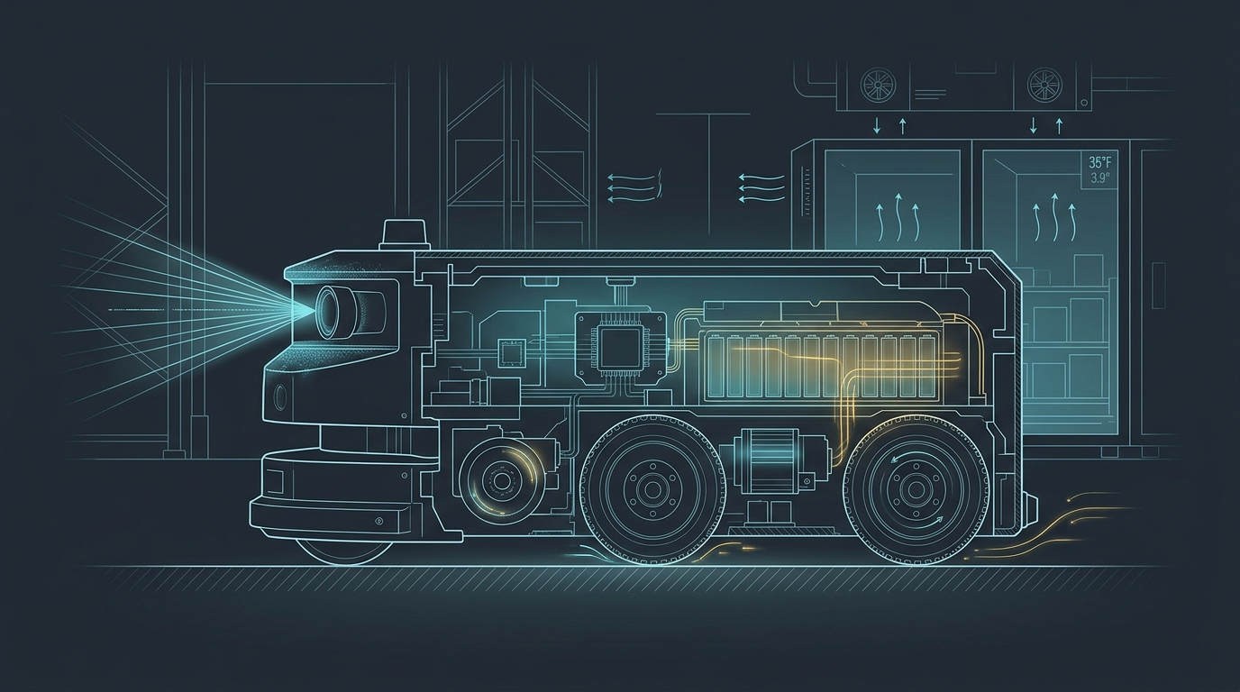
Automation principles must survive not just high speeds, but harsh physical environments. Deploying Autonomous Mobile Robots (AMRs) inside refrigerated dairy storage maintained at 35°F (1.6°C) illustrates how quickly theoretical software breaks down in cold physics.
1. Lithium Plating During Fast-Charging
At 35°F, lithium-ion electrolyte viscosity increases, dramatically impeding ion diffusion into the graphite anode. If high-current fast-charging is attempted while the cell core is cold, metallic lithium plates directly onto the anode surface. This permanently destroys battery capacity and creates dendritic crystal structures that cause internal short circuits.
Robotics platforms operating in cold storage must integrate thermal battery management systems (BMS) that pre-warm cell packs to before initiating charging protocols.
2. Optical Dew-Point Condensation
When robots travel across thermal transition zones between ambient loading docks and refrigerated rooms, optical protective glass drops below the dew point.
Condensation instantly coats LiDAR apertures and stereo camera lenses. The robot’s SLAM navigation algorithm perceives the fogged dome as an obstacle 3 inches away, locking the brakes and causing an uncommanded safety stop in a busy transit aisle. Active heating elements embedded in sensor bezels are non-negotiable.
3. Polyurethane Tread Hardening
Standard polyurethane drive wheels harden in low ambient temperatures. On polished concrete coated with thin moisture films, the coefficient of friction () drops by over 50%. Wheel slip corrupts dead-reckoning odometry, causing the robot’s localization filter to diverge. Softer, siped silicone-composite compounds are required to maintain traction and positional integrity.
Summary: The Architecture of Deterministic Scale
- Conveyance is kinematics, not conveyance steel: Managing S-curve acceleration ramps and jerk derivatives is the prerequisite for stable material handling.
- Optical registration requires edge-interrupt precision: Measuring dynamic parcel lengths and leading edges in real-time outperforms static cloud manifest assumptions.
- Dynamic gapping unlocks latent capacity: Replacing fixed temporal delays with mass-and-velocity kinematic calculations frees up 15% to 20% throughput from existing conveyor hardware.
- Digital twins kill the prototype risk: Simulating physics, friction, and actuator latency in virtual models validates PLC ladder logic before physical commissioning.
- Unified datasets unlock agentic operations: Breaking down silos between PLC registers, maintenance tickets, and business systems allows autonomous software agents to predict failures, balance flow, and orchestrate physical operations.
Technical Q&A
Q1: Why are S-curve acceleration profiles superior to linear acceleration ramps on conveyors?
A: Linear acceleration ramps exhibit instantaneous spikes in jerk (the rate of change of acceleration) at the start and end of the velocity transition. This sudden jerk overcomes the static coefficient of friction () between the package and the belt, causing slick items like polybags to slip and lose tracking registration. S-curve profiles round off the jerk transition, maintaining static friction and ensuring that the package’s physical position matches the PLC encoder count.
Q2: How do digital twins differ from standard 3D CAD or SCADA animation?
A: Standard 3D CAD is static geometry; SCADA animation is a delayed visualization of live states. A true digital twin is a physics-based, bi-directional simulation environment. It models mass, velocity vectors, mechanical friction, and pneumatic latency, allowing engineers to connect an actual or emulated PLC processor to virtual sensors and stress-test control algorithms under violent fault conditions without physical risk.
Q3: What makes an industrial automation dataset “agentic-ready”?
A: Traditional industrial data is trapped in cyclical PLC memory or siloed SCADA alarms that reset every shift. An agentic-ready dataset unifies high-speed sensor transitions, VFD telemetry, maintenance history, and parts inventory into a standardized, real-time relational event stream (e.g., via MQTT, WebSockets, or edge time-series databases). Autonomous AI agents can query this structured stream to detect subtle patterns, predict mechanical wear, and take deterministic operational actions.
Next Step: Consultative Engineering
Modern industrial excellence requires bridging the gap between shop-floor mechanical physics and high-level software logic.
- Explore our work in Industrial Projects & Systems.
- Read our manufacturing framework: The 5D Manufacturing Methodology.
- Connect with Aram Goganian on LinkedIn to discuss deterministic controls, digital twin modeling, and agentic industrial architectures.