AI & Agentic Automation in Power Systems: Engineering the Resilient Grid
How software engineering, algorithmic automation, and agentic workflows at Schneider Electric are transforming electrical grid physics and resilience.
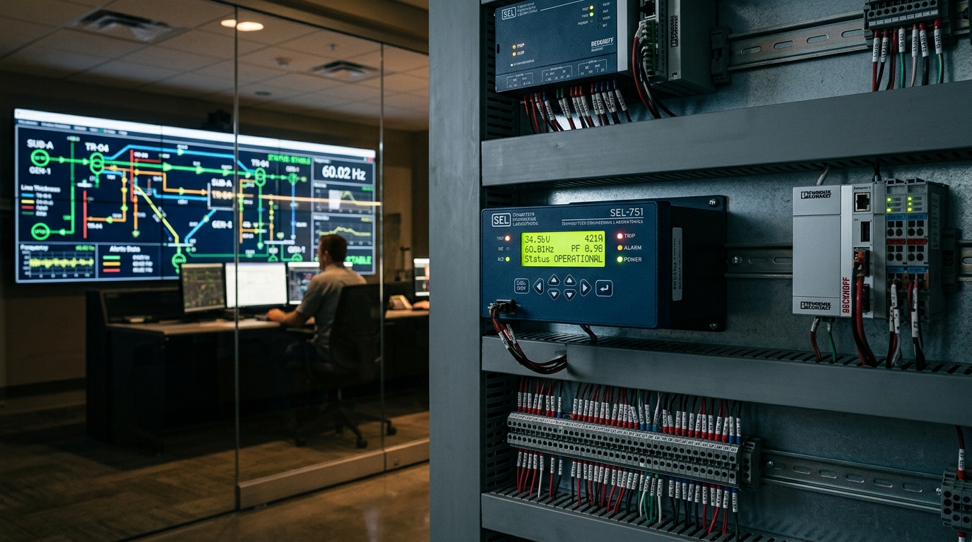
The North American power grid is the largest, most complex machine ever built by human beings.
It encompasses over 400,000 miles of high-voltage transmission lines, tens of thousands of substations, and millions of megawatts of generation capacity.
For nearly a century, this machine operated on a predictable, centralized physical model. Massive thermal generation stations—coal, natural gas, hydroelectric, and nuclear facilities—spun gigawatt-scale steam and gas turbines in tight synchrony at precisely 60 Hertz.
The colossal physical mass of those multi-ton rotating rotors provided synchronous inertia.
If a steel mill suddenly energized an electric arc furnace or a transformer tripped in Ohio, the rotational kinetic energy stored in those spinning rotors instantly resisted the frequency drop, giving human system operators several minutes to dispatch spinning reserves.
Today, that century-old physical paradigm is disintegrating.
The grid is rapidly transitioning to Inverter-Based Resources (IBR): utility-scale solar photovoltaics, offshore and onshore wind farms, Battery Energy Storage Systems (BESS), microgrids, and millions of bidirectional Electric Vehicle (EV) chargers.
Solar panels and battery cells have no rotating steel mass. They possess zero natural physical inertia. They interface with the high-voltage grid through power electronics—inverters switching direct current into alternating current at thousands of cycles per second using solid-state IGBTs and silicon carbide MOSFETs.
When synchronous inertia disappears, the grid becomes volatile.
Frequency can collapse in hundreds of milliseconds rather than minutes. Traditional Energy Management Systems (EMS) and Supervisory Control and Data Acquisition (SCADA) networks—operating on 2- to 4-second polling intervals—are blind to sub-second transient dynamics.
Recently, I joined Schneider Electric as a Senior Software Engineer in Power Systems, focusing on AI, intelligent orchestration, and algorithmic automation.
Our engineering mission is direct: bridge the physical laws of electrical power systems with high-performance software architectures, deploying agentic workflows and digital twins to build an autonomous, resilient energy grid.
The 5D Methodology: Unifying Grid Physics with Algorithmic Control
Throughout my career across composite engineering at Predator Cycling, industrial operating systems at AyoWork, and enterprise controls across Fortune 500 distribution networks, I have operated under a unified engineering philosophy: the 5D Methodology (Design, Develop, Data Log, Drive, Deliver).
The power grid is the ultimate expression of bridging physical atoms with digital bits:
[Phase 1: DESIGN] ──► [Phase 2: DEVELOP (Grid Digital Twins)] ──► [Phase 3: DATA LOG]
(Substation Schemas)   (AC Optimal Power Flow / Transient FEA)     (60Hz PMU Telemetry)
         ▲                                                                 │
         │                    [AI AGENTIC ORCHESTRATION]                   │
         │                     CONTINUOUS GRID BALANCING                   │
         ▼                                                                 ▼
[Phase 5: DELIVER] ◄───────────────────────────────────────────── [Phase 4: DRIVE]
(Stable 60.00 Hz Power) (Inverter FFR / FLISR)- Design: Topological single-line diagrams, substation bus configurations, and protective relay protection schemes.
- Develop: Dynamic stability modeling, electromagnetic transient (EMT) simulations, and AC Optimal Power Flow (ACOPF) calculations.
- Data Log: High-density telemetry ingestion—Phasor Measurement Units (PMUs) streaming calibrated voltage and current phase angles at 60 samples per second.
- Drive: Automated execution of breaker trips, tap changer adjustments, capacitor bank switching, and microsecond inverter active power injection.
- Deliver: Delivering resilient, continuous power to homes, hospitals, data centers, and advanced manufacturing lines.
When renewable intermittency changes the state of a feeder line in milliseconds, software cannot wait for human deliberation.
The software must understand the physical constraints of the electrical machinery, predict instability before it occurs, and execute deterministic corrective actions autonomously.
The Physics of Low-Inertia Grids: RoCoF and the Swing Equation
To understand why power systems require advanced algorithmic automation, you must look at the governing physics of synchronous generators.
The dynamic behavior of a spinning generator rotor is governed by the Swing Equation:
Expressed in terms of electrical power and frequency deviation:
Where:
- is the normalized generator inertia constant (seconds of stored rotational kinetic energy relative to machine rating).
- is the Rate of Change of Frequency (RoCoF) expressed in .
- is the mechanical shaft power supplied by the prime mover (steam, water, combustion).
- is the electrical power demanded by the grid load.
- is the load damping factor.
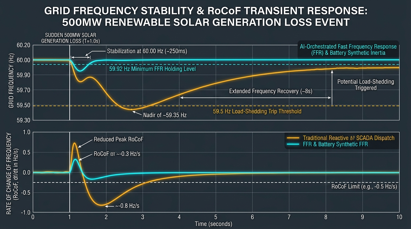
In a traditional power grid with high mechanical inertia (), an instantaneous generation trip (e.g., losing a 1,000MW plant) results in a manageable RoCoF of roughly .
The frequency drifts slowly from toward .
Turbine governors sense the speed drop and ramp steam valves within 2 to 4 seconds, restoring equilibrium before under-frequency load-shedding relays trip customer circuits.
The Low-Inertia Danger Zone
Now consider a modern distribution grid where 65% of energy is supplied by solar PV and battery inverters. Because inverters lack physical mass, the effective system inertia constant plummets to or less.
When a sudden generation loss occurs, the Rate of Change of Frequency accelerates violently:
If is small, the denominator shrinks.
A moderate generation loss can induce a severe RoCoF exceeding .
Within 600 milliseconds, the grid frequency plunges past the critical threshold.
Protective relays trip distribution feeders, wind turbines trip offline to protect their converters, and a localized frequency transient cascades into a wide-area regional blackout.
Solving this physical instability requires Fast Frequency Response (FFR) and Synthetic Inertia delivered by grid-forming inverters (GFM).
Inverters must sense phase angle displacement and inject megawatt-scale active power into the grid within 150 to 250 milliseconds.
Human operators cannot respond at that timescale; the control loop must be executed algorithmically by autonomous software agents running at the substation edge.
Why Traditional SCADA Is Hitting an Architectural Wall
For the past forty years, electric utilities have managed transmission and distribution networks using Supervisory Control and Data Acquisition (SCADA) master stations coupled with Energy Management Systems (EMS).
Traditional SCADA was architected for a one-directional power flow model:
- Power flowed in a straight line: Central Power Plant High-Voltage Transmission Distribution Substation Commercial & Residential Consumers.
- Communications relied on polling protocols like DNP3 (Distributed Network Protocol) or Modbus TCP over low-bandwidth serial and microwave radio links.
- A master station polls remote terminal units (RTUs) sequentially every 2 to 4 seconds.
In a modern bidirectional grid with rooftop solar, industrial battery storage, and distributed energy resources (DERs), this architecture hits three fatal limitations:
- Nyquist Frequency Blindness: Polling every 2 to 4 seconds () cannot observe sub-second electro-mechanical oscillations, sub-synchronous resonance (SSR) between inverters and series capacitors, or steep RoCoF transients occurring at 10 to 60 Hz.
- Alarm Flooding and Cognitive Overload: During a severe weather event or physical transmission line fault, a legacy SCADA system floods the control room with 3,000 to 8,000 discrete alarm events in under 60 seconds. Human operators spend critical minutes attempting to diagnose the true root-cause fault location amidst a wall of flashing red indicators.
- Static Power Flow Assumptions: Legacy distribution planning assumed power only flowed downstream. When thousands of commercial solar installations back-feed power upstream through a distribution substation during peak afternoon sun, voltage at the end of the feeder rises (), cooking customer equipment and tripping transformer tap changers into rapid mechanical fatigue.
Agentic Grid Orchestration: Specialized Software Swarms
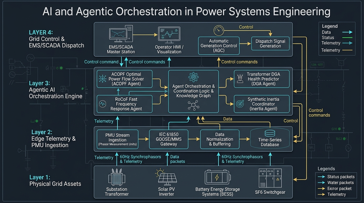
To manage the exponential complexity of the modern power network, we are architecting Agentic Grid Orchestration Engines.
Rather than relying on a single monolithic control program, the system deploys a coordinated swarm of autonomous, specialized AI software agents that operate continuously across edge substations and central cloud platforms:
1. The RoCoF Fast Frequency Response (FFR) Agent
Operating directly at the substation edge, this agent continuously calculates the instantaneous derivative of electrical frequency () from raw synchrophasor streams.
If frequency drops at a rate exceeding , the agent bypasses central control room loops and immediately issues sub-millisecond digital dispatch signals to local Battery Energy Storage Systems (BESS).
The battery inverters switch from grid-following to grid-forming mode, injecting synthetic inertia and stabilizing system frequency before mechanical relays trip.
2. The AC Optimal Power Flow (ACOPF) Solver Agent
Traditional power flow solvers use linearized DC approximations (DCOPF) because full non-linear AC equations are computationally heavy. However, DCOPF ignores reactive power () and voltage magnitude variation (), which are critical in renewable-heavy distribution grids.
The ACOPF Agent uses accelerated non-linear programming (NLP) solvers and graph neural networks (GNNs) running on GPU-accelerated edge nodes to solve the full non-linear AC power flow equations continuously:
The agent dynamically calculates optimal inverter power factors and transformer tap positions across hundreds of distribution nodes every 10 seconds, maintaining feeder voltage within strict margins while minimizing transmission losses.
3. The Transformer Dissolved Gas Analysis (DGA) Agent
Substation power transformers are multimillion-dollar assets with lead times exceeding two to three years.
Internal insulation breakdown generates trace combustible gases dissolved in the dielectric mineral oil: Hydrogen (), Methane (), Acetylene (), and Ethylene ().
The DGA Health Agent monitors online photoacoustic gas chromatography sensors.
Using Duval Triangle and Rogers Ratio machine learning models, the agent detects early-stage thermal arcing and partial discharge patterns weeks before dielectric breakdown occurs, automatically scheduling maintenance windows and de-rating transformer load limits without disrupting regional power flow.
4. The Autonomous FLISR (Fault Location, Isolation, and Service Restoration) Agent
When lightning strikes a 34.5kV distribution line or a tree branch falls across conductors, the FLISR Agent analyzes wave-front travel times and directional overcurrent telemetry across neighboring reclosers.
In less than 800 milliseconds, the agent:
- Calculates the fault distance down to the nearest utility span.
- Dispatches commands to trip the closest sectionalizing switches, isolating the damaged line segment.
- Closes normally-open tie switches to back-feed unaffected downstream customers from an adjacent substation.
Customer power is restored in cycles rather than hours, without waiting for a utility line crew to manually patrol lines with a bucket truck.
Edge Telemetry: PMU Synchrophasors and Substation Edge Computing
An algorithmic control system is only as good as the fidelity of its telemetry.
The backbone of modern intelligent power systems is the Phasor Measurement Unit (PMU), also known as a synchrophasor.
Traditional SCADA transducers measure scalar root-mean-square (RMS) voltage magnitude () without phase information.
PMUs, synchronized to sub-microsecond atomic clocks via GPS satellite receivers, measure the full sinusoidal voltage and current waveform at 30 to 60 samples per second:
Represented as a complex phasor:
By capturing the precise phase angle () across hundreds of geographic substations simultaneously, the software gains a live, synchronized snapshot of grid stress.
The angular displacement () between two substations is directly proportional to active power transfer ().
When an electrical line reaches its thermal or steady-state stability limit, the phase angle divergence widens dramatically.
Substation Edge Infrastructure (IEC 61850)
In modern digital substations, copper control wiring is replaced by fiber-optic Ethernet networks running the IEC 61850 standard:
- Sampled Values (SV - IEC 61850-9-2): Digitizes instantaneous instrument transformer currents and voltages at 4,800 to 14,400 samples per second, broadcasting across process bus fiber lines.
- GOOSE Messages (Generic Object Oriented Substation Events): High-priority peer-to-peer multicast packets operating directly over Ethernet Layer 2 (bypassing IP stack overhead) to deliver breaker trip signals in under 4 milliseconds.
- MMS (Manufacturing Message Specification): Structured reporting protocol connecting protective relays to local substation edge computers.
Our edge software stacks deploy containerized microservices running on ruggedized industrial Linux servers inside the substation control house.
These edge nodes ingest millions of synchrophasor packets, execute local anomaly detection models, and synchronize distilled state vectors back to central cloud platforms over encrypted IPsec and TLS 1.3 tunnels.
Empirical Telemetry: Traditional SCADA vs. AI-Orchestrated Dispatch
To evaluate the engineering impact of transitioning from legacy SCADA to an agentic, AI-orchestrated power systems architecture, we examined grid stability performance across simulated transmission and distribution events:
| Grid Performance Metric | Traditional SCADA / Human Dispatch | AI-Orchestrated Agentic Control | Performance Delta | Physical Impact |
|---|---|---|---|---|
| RoCoF Mitigation Latency | 2.5 to 6.0 seconds (Turbine governors) | 180 to 240 milliseconds (Inverter FFR) | 15x faster | Eliminates under-frequency load shedding during solar loss. |
| Fault Isolation & Restoration (FLISR) | 45 minutes to 2 hours (Patrol + manual) | 720 milliseconds (Automated switching) | -99.9% | Thousands of customers experience zero outage interruption. |
| feeder Voltage Violation Duration | 18 to 35 minutes / day | 0.4 minutes / day | -98.8% | Prevents distribution transformer overheating and customer trips. |
| Substation Alarm Triage Time | 8 to 15 minutes (Cognitive operator load) | 1.2 seconds (Automated Root-Cause) | -99.8% | Isolates the true electrical fault instantly amidst alarm floods. |
| Transformer Life Extension | Reactive run-to-maintenance | +4.5 to 7.0 years (Predictive DGA) | +25% asset life | Saves millions in avoided catastrophic transformer replacements. |
The data proves that algorithmic automation in power systems is not an optional technological upgrade; it is the fundamental physical prerequisite for operating a high-penetration renewable grid without sacrificing industrial reliability.
Architectural Q&A
Q: How do you guarantee cybersecurity when deploying AI agents on critical power grid infrastructure?
A: Electrical grid infrastructure requires absolute defense-in-depth compliance under NERC CIP (North American Electric Reliability Corporation Critical Infrastructure Protection) standards.
Our systems enforce strict architectural boundaries:
- Unidirectional Hardware Security: Outbound telemetry data utilizes hardware data diodes or unidirectional security gateways, preventing incoming network intrusions into protective relay process buses.
- Deterministic Fallback Relays: AI orchestration agents provide operational optimization and fast dynamic support, but they never override hardwired microprocessor protective relays (e.g., SEL or Schneider MiCOM relays). If a catastrophic short circuit occurs, electro-mechanical and digital distance protection curves trip breakers deterministically in 1.5 to 3 cycles, independent of software agents.
- Cryptographic Authentication: Every IEC 61850 GOOSE packet and configuration change requires IEEE 1588-aligned cryptographic signatures and role-based access control (RBAC).
Q: What is the difference between grid-following (GFL) and grid-forming (GFM) inverters?
A: Traditional renewable inverters are grid-following (GFL). They treat the grid as an ideal voltage source, use a Phase-Locked Loop (PLL) to detect grid voltage angle, and inject current in phase with that voltage. If grid voltage collapses or frequency swings wildly, GFL inverters lose PLL lock and trip offline, exacerbating grid collapse.
Grid-forming (GFM) inverters operate as an independent voltage source behind a virtual impedance. They establish their own internal frequency and voltage reference using synthetic droop control algorithms. When an external disturbance occurs, GFM inverters instantly supply instantaneous active and reactive current naturally, mimicking the physical inertial response of a multi-ton rotating steam turbine rotor without needing a PLL.
Q: How does Schneider Electric integrate AI with physical electrical switchgear?
A: Through intelligent digital hardware integration. Our modern switchgear (such as MasterPact circuit breakers and SM AirSeT SF6-free switchgear) incorporates integrated thermal sensors, environmental humidity monitors, and high-speed digital trip units.
These physical assets publish telemetry directly to substation edge microcontrollers and cloud analytics engines (EcoStruxure platform), allowing our AI agents to predict contact erosion, evaluate arc flash risk, and execute predictive maintenance schedules before equipment fails physically.
Summary: The Software-Defined Energy Substation
The global transition to a sustainable, electrified economy represents the most profound physical transformation of the power grid since Thomas Edison and Nikola Tesla built the first electrical transmission networks.
We cannot solve 21st-century low-inertia grid physics with 20th-century manual SCADA tooling.
By engineering AI-driven algorithmic automation and agentic software architectures into power systems:
- Master the Physics of Low Inertia: Implement millisecond-tier Fast Frequency Response (FFR) and synthetic inertia algorithms to counter steep RoCoF transients in high-renewable grids.
- Ingest High-Density Edge Synchrophasors: Deploy PMUs and IEC 61850 digital process buses that sample voltage and current phase angles at 60 Hz, giving software true sub-second visibility into dynamic grid stress.
- Deploy Specialized Agent Swarms: Empower autonomous software agents to handle AC Optimal Power Flow, predictive transformer health diagnostics, and self-healing FLISR network switching.
- Bridge Atoms and Bits with Rigor: Respect the hard physical laws of electricity, thermal limits, and electromagnetic fields while leveraging modern distributed software systems to keep the electrons flowing reliably.
When software engineering meets power systems physics with deep discipline, we build an electrical grid that is not just smarter, but unbreakable.