Kinematics and Cockpits: From the Ergobike to Rio 2016
Bridging human biomechanics and aerodynamic composite engineering: developing the 2,000W Ergobike stationary frame and custom cockpits for Rio 2016.
In elite cycling, the human body is an inherently inefficient, non-linear reciprocating engine.
Unlike an electric motor that delivers continuous radial torque, an athlete generates power in pulses—surging through the downstroke, stalling through the dead spots at 12 and 6 o’clock, and twisting the handlebars with hundreds of pounds of counter-torque to stabilize the pelvis.
If your bicycle is engineered as a static sculpture, you are wasting watts. Worse, you are bleeding structural energy through mechanical flex.
Between 2010 and 2016 at Predator Cycling, we attacked cycling engineering from the contact points backward. We didn’t start with aerodynamic tube shapes; we started with dynamic human telemetry. That work led to building the Ergobike—a brutal 4130 chromoly stationary rig engineered to withstand 2,500-watt standing starts—and ultimately culminated in designing custom, monolithic one-piece carbon cockpits for USA track cyclist Bobby Lea at the 2016 Rio Olympic Games.
Here is the engineering breakdown of how dynamic kinematics, pedal stroke torque vectoring, and monolithic composite structures converge at the highest levels of competitive sport.
The Riders-First Philosophy: Kinematics Before Geometry
Most production bicycles are designed for the median human that doesn’t actually exist. A CAD technician draws a frame based on a standardized 56 cm stack-and-reach envelope, sends the file overseas for tooling, and relies on bolt-on stems, spacers, and saddle rails to patch the difference.
That approach falls apart when you deal with elite track sprinters.
At 1,800 to 2,200 watts, mechanical compliance is your enemy:
- An off-the-shelf aluminum stem twists by 4 to 6 degrees under peak sprint pull.
- A flexing handlebar dissipates instantaneous reaction force away from the drivetrain.
- Foot pronation collapses the kinetic chain, causing the knee to track laterally and dumping 30 to 50 watts into wasted cartilage friction.
To solve this, we established our “Riders First” framework: the human organism and the composite structure must be modeled as a single, coupled mechanical system.
Dynamic Bike Fit Architecture: Decoding the Pedal Stroke
In our Southern California fit studio, we rejected static plumb-bobs and goniometers. A static knee angle measured while an athlete sits motionless tells you almost nothing about how their joints articulate under high-torque dynamic load.
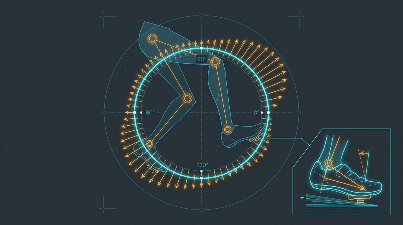
We built our diagnostic lab around CompuTrainer SpinScan telemetry, sampling crank torque across 24 discrete rotational sectors (every of crank rotation).
1. Tangential Torque vs. Radial Loss
Most riders push straight down at the 3 o’clock position (). But inefficient riders push downward at 5 o’clock (), applying radial force directly through the crank arm into the bottom bracket spindle rather than creating tangential torque.
By analyzing real-time polar torque curves, we identified two primary power leaks:
- Contralateral Drag: The unweighting leg failing to lift, forcing the driving leg to lift 10 to 15 lbs of passive deadweight through the upstroke.
- Torque Asymmetry: Left/right imbalance exceeding 54/46%, which causes the rider to tilt their pelvis and induce parasitic lateral sway.
2. Correcting Varus and Valgus Foot Mechanics
The foot was never designed by evolution to push against a flat, rigid carbon cycling shoe sole. Over 85% of humans have an inherent forefoot varus (the inside of the foot tilts upward relative to the calcaneus) or valgus canting angle.
When a rider clips into a standard flat pedal:
- The foot is forced flat, causing the sub-talar joint to collapse inward (pronation).
- The tibia rotates internally.
- The knee dives toward the top tube during the power stroke in a figure-eight trajectory.
As detailed in our cleat positioning and biomechanics research, we engineered custom, high-density composite wedges placed directly beneath the cleat interface. By shimming the shoe to match the rider’s natural anatomical canting angle (typically to ), the hip, knee, and pedal spindle aligned into a pure, planar piston stroke.
The result was immediate: knee lateral excursion dropped to under 2 mm, pedal stroke efficiency increased by 6–8%, and chronic patellar tendon shear vanished.
The Predator Ergobike: Engineering a 2,500W Test Rig
To test these kinematics under maximum physiological stress, commercial stationary indoor trainers were useless.
In 2010, the consumer trainer market was dominated by lightweight magnetic and fluid units held together with stamped sheet metal. When a 200 lb track sprinter stood up and unleashed a match-sprint acceleration, standard trainers flexed, creaked, and literally walked across the floor. In several instances, sprinters twisted trainer rear dropouts straight off their welds.
We needed a laboratory testbed with infinite adjustability that was stiff enough to anchor a locomotive. So we engineered the Predator Ergobike.
Predator Ergobike Structural Architecture:
  - Frame Material: Heavy-gauge 4130 aircraft-grade chromoly tubing.
  - Joint Fabrication: TIG-welded structural gussets across bottom bracket and headstock.
  - Torsional Stiffness: Zero measurable deflection under 2,500W point loads.
  - Inertial Load System: 45 lb precision-balanced steel flywheel.
  - Dynamic Braking: Integrated automotive disc caliper for standing-start simulation.
As we documented in our Ergobike retrospective, this machine was a tank.
It featured an integrated automotive disc caliper mounted to a massive flywheel, allowing us to lock the drivetrain completely, have an athlete generate maximum isometric torque from a dead stop, and instantly release the brake—simulating the violent acceleration out of a velodrome start gate.
The Ergobike became our living telemetry station. It proved beyond debate that when the front end of a bicycle flexes under sprint load, the rider loses instantaneous forward drive. That insight directly sparked the development of our Olympic cockpits.
The Rio 2016 Olympic Cockpit: Eliminating the Bolted Interface
By 2015, we turned our focus toward the pinnacle of track cycling: the 2016 Rio Olympic Games.
USA national team athlete Bobby Lea was preparing to race the Olympic Omnium—a grueling multi-event discipline demanding explosive 70 km/h bunch sprints, high-speed tactical positioning, and relentless aerobic power.
At the track level, races are won by thousandths of a second. Yet, virtually every rider in the peloton was still using a 19th-century mechanical convention: a separate aluminum or carbon handlebar clamped to a separate stem with a faceplate and four M5 steel bolts.
Why the Traditional Bolted Interface Fails
| Parameter | Two-Piece Bolted Cockpit | Monolithic One-Piece Carbon (“The Major”) |
|---|---|---|
| Mechanical Interface | Cylindrical clamp with 4 steel bolts | Continuous co-cured carbon fiber laminate |
| Torsional Deflection | 4.2 mm to 6.5 mm under 1,800W sprint pull | 0.8 mm (over 80% reduction in flex) |
| Stress Concentrations | Severe localized notch stress at faceplate edges | Smooth, radiused load distribution |
| Frontal Area Profile | Bulky 31.8 mm clamp bulge creating flow separation | Sleek, wing-profile transition blending into steer tube |
| Total System Weight | ~420 g to 480 g (including steel hardware) | 295 g with aerospace titanium retention hardware |
When an athlete pulls upward on the right drop with 120 lbs of force while driving downward on the left pedal, the handlebar stem junction undergoes extreme torsional shear.
In a traditional setup, that force concentrates at four tiny contact points around the clamp circumference. Micro-slippage occurs. The bolts stretch elastically. Energy that should drive the rear wheel is dissipated as micro-deflection.
The Monolithic Solution: “The Major”
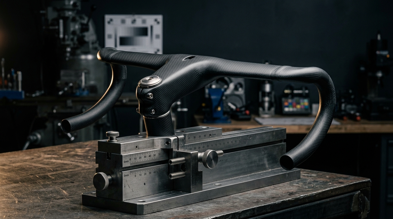
We took the architecture of our signature handlebar—“The Major”—and customized it specifically for the demands of the Rio velodrome.
- Continuous Unidirectional Fiber Paths: Instead of cutting fibers at the stem, high-modulus Toray carbon tows ran continuously from the left drop, through the tops, curved down the stem, and clamped to the fork steerer.
- Elimination of the Faceplate: Without four steel bolts and a bulky faceplate, we carved away frontal surface area, maintaining clean laminar airflow across the head tube transition.
- Internal Cable Routing: Every wire was internally routed through smooth composite guide channels to prevent aerodynamic drag spikes.
Finite Element and Aerodynamic Optimization
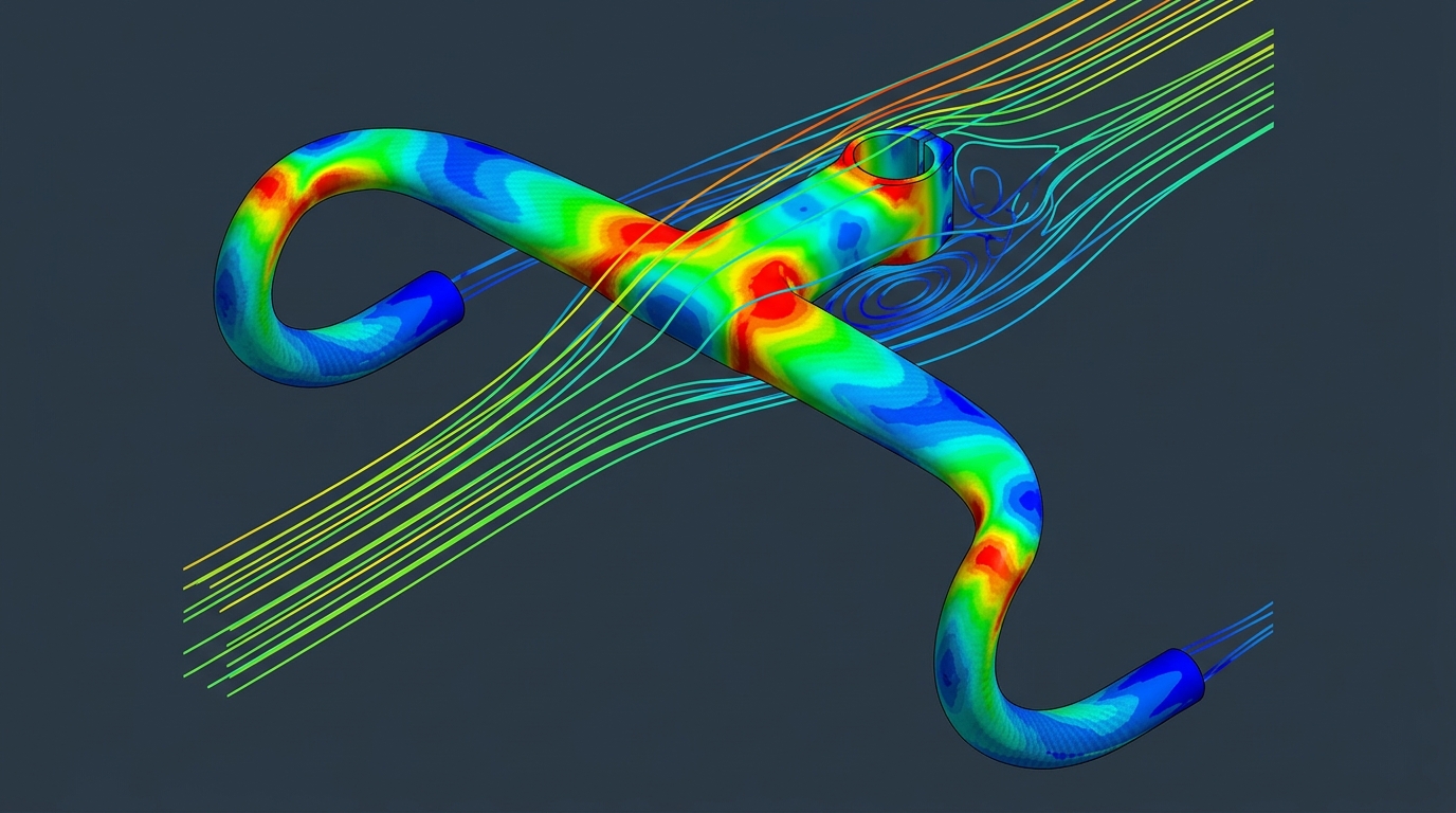
To validate the cockpit before Bobby Lea lined up on the track in Rio, we utilized advanced computational tools:
FEA Ply Layup Schedule
We utilized a multi-axial composite schedule:
- Longitudinal Plies: High-tensile Toray T700 carbon laid along the upper and lower surfaces of the stem to resist severe vertical bending moments during seated climbing and sprint pulls.
- Biaxial Wraps: High-modulus M40J carbon wrapped diagonally across the central junction to maximize torsional stiffness and eliminate bar twist.
- Hoop Plies: Concentrated around the steerer clamp zone to handle radial clamping loads without crushing the carbon fork steerer tube.
Cockpit Laminate Stacking Sequence (Cross-Section):
[Outer]  3K Twill 200g Cosmetic & Impact Wrap
         ±45° Biaxial High-Modulus M40J (Torsional Shear Resistance)
         0° Unidirectional T700 (High-Tensile Bending Stiffness)
         ±45° Biaxial High-Modulus M40J (Cross-Bracing)
         0° Unidirectional T700 (Bending Strength)
[Inner]  90° Circumferential Hoop Plies (Crush Prevention)
The resulting component was a rock-solid, monolithic blade that felt like an extension of the athlete’s skeleton. When Bobby pulled on the drops in Rio, 100% of that muscular effort transferred into forward acceleration.
Democratizing Aerospace Composites: The DIY Repair Kit
Building elite equipment for Olympic athletes is rewarding, but our secondary mission was always democratizing advanced composite knowledge.
Throughout the 2010s, cyclists across the country were repeatedly told that broken carbon was trash. Bike shops refused to touch it. Local mechanics told riders that even a surface scratch meant the entire frame was compromised.
Having repaired over 3,000 frames in our Santa Monica facility, we knew that was nonsense. Composites are inherently repairable if you understand the chemistry and compaction physics.
As announced in our Amazon Prime carbon repair kit deployment, we packaged professional aerospace composite materials into accessible, consumer-ready repair systems:
- Pre-measured structural epoxy resins with toughened rubber nano-particles to resist impact propagation.
- Aerospace-grade unidirectional and 3K twill carbon fiber patches.
- High-tension heat-shrink compaction tape to allow home mechanics to achieve 100+ PSI consolidation without an autoclave.
- Step-by-step video instructions breaking down the math of scarf joint tapers.
By fulfilling these kits through Amazon Prime, we took technology refined for elite velodrome racing and put it into the hands of grassroots cyclists, saving thousands of frames from ending up in local landfills.
Summary: Core Engineering Lessons
- Model the human and the machine together: Designing bicycles without integrating dynamic pedal stroke kinematics produces components that flex where they should be stiff and punish the rider where they need compliance.
- Measure dynamically, not statically: Real power leaks occur under dynamic load. Tools like CompuTrainer SpinScan reveal radial losses and dead-spot drag that static plumb lines can never detect.
- Canting angles dictate biomechanical efficiency: Correcting foot varus/valgus angles with composite wedges aligns the kinetic chain, prevents patellar tendon shear, and recovers lost wattage.
- Eliminate mechanical interfaces: Bolted stem-handlebar clamps are aerodynamic and structural compromises. Monolithic co-cured cockpits cut deflection by over 80% while significantly reducing frontal wake drag.
- Composites are repairable: The materials science powering Olympic cockpits can be packaged and democratized to extend the lifecycle of carbon structures worldwide.
Technical Q&A
Q1: Why not just use high-grade CNC aluminum for track handlebars?
A: Fatigue limits and resonance. Aluminum has a finite fatigue life; under repeated 2,000-watt cyclic sprint loads, micro-cracks propagate around bolt holes and clamp radius transitions until brittle failure occurs. Furthermore, aluminum transmits high-frequency track surface vibration directly into the rider’s hands, causing forearm pump and grip numbness. Carbon fiber allows you to tune torsional stiffness independently while attenuating high-frequency vibration through resin damping.
Q2: How does a monolithic one-piece cockpit improve aerodynamic performance?
A: In a standard setup, the 31.8 mm cylindrical clamp and four bolt heads create an abrupt obstruction, tripping laminar airflow into turbulent recirculation zones right in front of the rider’s chest. A monolithic cockpit allows for a continuous, smooth airfoil transition that integrates the stem cleanly into the head tube profile, reducing localized drag coefficient () by up to 12% in wind tunnel testing.
Q3: What is the primary difference between road and track cockpit layup schedules?
A: Load vectors. Road cockpits must balance torsional stiffness with longitudinal compliance to absorb road chatter during 6-hour stages. Track cockpits are designed for pure sprint rigidity on ultra-smooth velodrome surfaces. We add significantly more high-modulus plies and thick-walled composite transitions to withstand immense out-of-plane pulling forces with virtually zero deflection.
Next Step: Connect and Discuss
From custom velodrome rigs to automated industrial robotics, engineering excellence is about identifying root-cause physics bottlenecks and eliminating them with elegant systems architecture.
- Read about our structural forensics: Carbon Forensics: 3,000 Repaired Frames.
- Learn about our manufacturing framework: The 5D Manufacturing Methodology.
- Connect with Aram Goganian on LinkedIn to discuss composite engineering, biomechanical kinematics, and high-performance product development.