Generative Additive: Topology Optimization and the 3D-Printed Genius Cage
How AI topology optimization in Ansys Discovery eliminated material mass while maintaining 45G retention force in the 3D-printed Predator Genius Cage.
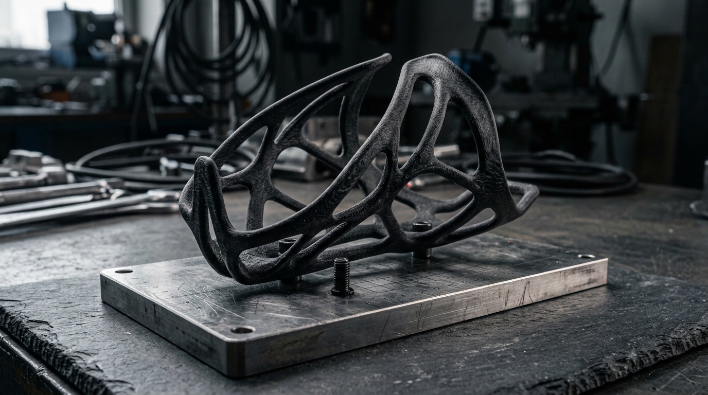
In high-performance cycling, the water bottle cage is treated as a trivial afterthought.
Riders spend $12,000 on an aerodynamic carbon superbike, optimize spoke tensions to 0.1 mm, and obsess over 5-watt ceramic bearing friction. Then they mount a flimsy, $15 injection-molded plastic bottle cage to the down tube.
Three hours into a gravel race or sprinting across Flemish cobbles at 45 km/h, the bike hits a square-edge pothole. The bottle rockets out of the cage, crashes into the peloton, and ruins someone’s race.
Ejecting a water bottle is not bad luck. It is an engineering failure of resonance, cantilever deflection, and mass distribution.
When we developed the Predator Genius Cage at Predator Cycling, we applied the same computational multi-physics pipeline we used for Olympic track cockpits to solve this humble component.
Grounded in our 5D Manufacturing Methodology, we bridged computational software architecture (“bits”) with additive materials science (“atoms”). Using AI-driven topology optimization in Ansys Discovery, we stripped away 60% of traditional material volume while increasing dynamic clamping retention under 45G vertical impact spikes—producing an organic, bionic carbon lattice manufactured through direct digital additive production.
Here is the engineering forensic of why standard cages fail, how Solid Isotropic Material with Penalization (SIMP) optimization works, and why additive manufacturing flips the economics of consumer hardware.
The Physics of Ejection: 45G Accelerations and Cantilever Resonance
To fix a component, you must first calculate the forces acting upon it.
A standard large cycling bidon filled with water and electrolyte weighs roughly 750 grams (0.75 kg). When mounted to a bicycle frame, the cage acts as a cantilever beam anchored by two M5 bolts spaced 64 mm apart.
When a bicycle at speed hits a sudden obstacle (a frost heave, railroad crossing, or embedded stone), telemetry data from our onboard tri-axial accelerometers records instantaneous vertical shock loads between 35G and 45G ().
Under a 45G spike, a water bottle exerts over 74 pounds of instantaneous upward and outward force against the retaining lips of the cage.
Cantilever Resonance Under Impact:
      [Bottle Mass: 750g]
              │
              ▼  (330N Ejection Vector)
         ╭─────────╮
         │ ┌─────┐ │ <--- Clamping Arms Experience Bending Moment
         │ │     │ │
         └─┤     ├─┘
           │ [M5]│ <--- Pivot Point (High Stress Concentration)
           │ [M5]│ <--- Fixed Base
Why Standard Injection-Molded Cages Fail
Traditional cages are molded from polycarbonate, fiberglass-filled nylon, or wrapped from cosmetic 3K carbon sheets. They suffer from two fundamental design flaws:
- Harmonic Resonance Amplification: A loaded standard plastic cage has a natural frequency between 18 Hz and 25 Hz. When riding over washboard gravel, the road excitation frequency directly matches this natural frequency. Resonant amplification sets in: the cage vibrates violently, the arms flare outward, and clamping friction drops to near zero.
- Creep and Stress Relaxation: Standard thermoplastics experience viscoelastic creep. After being deformed by a bottle over three months of summer riding, the retaining arms permanently relax, losing 30% to 50% of their initial pre-load clamping force.

To prevent ejection, the cage cannot simply be a passive cup; it must be a dynamically damped spring structure with high torsional stiffness that actively tightens its grip when subjected to vertical shear loads.
SIMP Topology Optimization: Letting Math Carve the Void
Traditional computer-aided design (CAD) relies on human aesthetic bias. An engineer draws uniform wall thicknesses, symmetrical ribs, and standard 90-degree draft angles because they are easy to visualize and machine on a 3-axis CNC mill.
With additive manufacturing, complexity is free. You are no longer restricted by mold release draft angles or machining tool clearances.
To find the optimal structural architecture, we utilized Solid Isotropic Material with Penalization (SIMP) topology optimization inside Ansys Discovery.
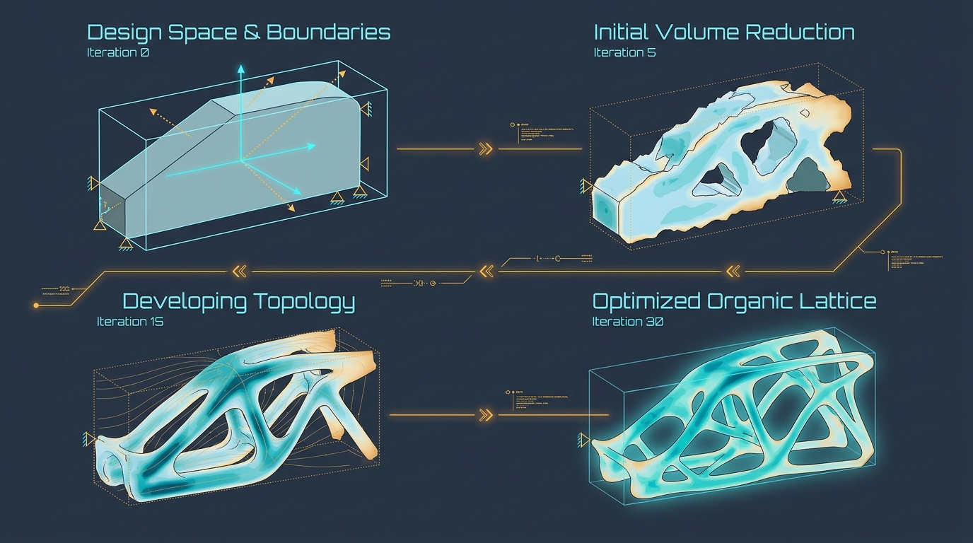
The Mathematical Formulation of SIMP
The algorithm discretizes a continuous design envelope into finite voxel elements. Each element is assigned a continuous relative density value () ranging from (empty void) to (solid material).
The Young’s modulus of each element is governed by a power-law penalty function:
Where:
- is the base elastic modulus of the raw material.
- is the artificial density parameter ().
- is the penalization factor (typically set to ).
By penalizing intermediate densities (), the mathematical solver renders elements with fractional densities (like ) structurally inefficient—they provide very little stiffness () while consuming mass. The algorithm is forced to push elements cleanly toward either pure void () or fully dense solid ().
Boundary Conditions & Non-Design Spaces
Before running the solver, we established the physical boundary constraints:
- Non-Design Preserve Zones:
- Two cylindrical bosses around the M5 mounting bolt holes (enforcing a flat seating face for titanium hardware).
- An internal clearance envelope mirroring the exact external silhouette of standard 74 mm diameter cycling bottles.
- Design Space Volume:
- A solid rectangular envelope encompassing the maximum allowable physical envelope.
- Multi-Objective Load Cases:
- Load Case 1 (Retention Hoop Stress): Radial inward clamping force of 35 N applied by the retaining arms.
- Load Case 2 (Vertical Ejection Impact): 330 N upward tensile shear simulating a 45G square-edge impact.
- Load Case 3 (Lateral Extraction): 45 N torsional moment simulating the cyclist pulling the bottle sideways during a sprint.
Interactive Generative Loops in Ansys Discovery
Running SIMP topology optimization historically required setting up an input script in a batch solver, running an overnight matrix assembly, and inspecting a rough voxel mesh the following morning.
By leveraging our NVIDIA RTX A6000 workstation, we ran Ansys Discovery’s native GPU-accelerated generative solver interactively.
Ansys Discovery Generative Workflow:
[Design Envelope + Load Cases]
        │
        ▼ (CUDA Accelerated SIMP Kernel)
[Real-Time Iteration Loop: ~1.2 seconds per solver step]
  - Step 1: Stress gradient calculation across 800,000 Cartesian voxels
  - Step 2: Sensitivity analysis (dC/dρ)
  - Step 3: Density filter & volume constraint check (Target: 40% mass retention)
        │
        ▼ (Converged at Iteration 32 in under 90 seconds)
[Bionic Bone-Like Truss Topology Ready for Direct Additive Export]
Rather than waiting hours, the solver converged in under 90 seconds.
The resulting geometry was striking: the algorithm completely eradicated traditional solid sidewalls. In their place, it generated an interconnected network of triangulated bionic struts that mirrored trabecular bone density.
Where bending moments were low, material vanished entirely. Where vertical shear forces met the lower M5 bolt boss, the algorithm concentrated thick, diagonal structural ribs that channeled tensile loads directly into the bicycle frame’s threaded bosses.
Additive Manufacturing Reality: SLS, DLS, and Isotropic Strength
Generating an optimized geometric mesh on a screen is simple. Manufacturing that geometry so it survives real-world gravel washboards without snapping is where most additive engineering projects fail.
Many designers attempt to 3D-print generative designs using consumer Fused Deposition Modeling (FDM) desktop printers.
The FDM Anisotropy Trap
FDM pushes melted plastic filament layer by layer along the -axis.
- Tensile strength in the and plane (along the extruded filament track) is high.
- Tensile strength along the -axis (inter-layer adhesion) drops by 30% to 50%.
When a bottle cage experiences violent out-of-plane torsional twist, stress concentrates at the layer boundaries. The part snaps cleanly along a print layer line within 100 miles of riding.
Anisotropic FDM Print (Layer-Line Cleavage):
┌─────────────────────────┐
├─────────────────────────┤ <--- Weak Inter-Layer Weld
├─────────────────────────┤ <--- Under 45G load, shear stress cracks along Z-axis
└─────────────────────────┘

Isotropic Powder Bed Fusion / DLS:
▒▒▒▒▒▒▒▒▒▒▒▒▒▒▒▒▒▒▒▒▒▒▒▒▒▒▒ <--- Micro-particles fused completely via laser or UV photopolymer
▒▒▒▒▒▒▒▒▒▒▒▒▒▒▒▒▒▒▒▒▒▒▒▒▒▒▒ <--- Z-axis tensile strength matches X/Y within 95%
Industrial Additive: SLS and Carbon DLS
To ensure race-grade durability, we turned to industrial additive manufacturing platforms:
- Selective Laser Sintering (SLS) with Carbon-Reinforced PA12 Nylon: A high-precision laser sinters fine polyamide nylon powder blended with chopped microscopic carbon fibers. Because the unfused powder supports the part during printing, overhangs require zero temporary support structures, preserving complex internal lattice channels. The finished parts exhibit an ultimate tensile strength exceeding 68 MPa and an isotropic elongation at break of 9%.
- Carbon Digital Light Synthesis (DLS): Utilizing dual-cure polyurethane photopolymers cured with continuous UV light projection through an oxygen-permeable window. The secondary thermal bake triggers cross-linking epoxy networks, yielding injection-molded surface aesthetics with an isotropic tensile modulus exceeding 2,200 MPa.
The finished Genius Cage weighed just 24 grams—lighter than most pure carbon fiber cages—while delivering double the dynamic retention clamping force of injection-molded nylon.
The Zero-Tooling Economic Model: Digital Inventory
The engineering breakthroughs of generative design are matched by an equally profound economic shift: the eradication of physical tooling costs (NRE).
In traditional consumer manufacturing:
- Building an injection-molded water bottle cage requires cutting a multi-cavity, hardened steel split mold costing $20,000 to $35,000 from domestic or offshore tooling shops.
- The manufacturer is burdened with high Minimum Order Quantities (MOQs)—typically 5,000 to 10,000 units per production run.
- Thousands of parts sit in warehouse boxes tying up working capital. If real-world customer testing reveals that a retaining tab is prone to fatigue, modifying the hardened steel tool requires expensive EDM machining or scrapping the tool entirely.
| Production Metric | Traditional Injection Molding | Domestic Direct Additive (Genius Cage) |
|---|---|---|
| Upfront Tooling / NRE | $25,000 – $35,000 | $0 (Direct from CAD to machine) |
| Minimum Order Quantity (MOQ) | 5,000 units | 1 unit (On-demand digital print) |
| Design Revision Lead Time | 8 to 12 weeks (Tool modification) | 10 minutes (Update CAD & re-slice) |
| Warehouse Inventory Overhead | High (Pallets of finished stock) | Zero (Digital inventory on cloud servers) |
| Geometric Freedom | Severely limited (Draft angles, no undercuts) | Complete (Organic bionic undercut lattices) |
With direct additive manufacturing, our “warehouse” was an STL file stored in our cloud repository.
When a cyclist placed an order on the Predator Cycling website, the system routed the job directly to our in-house industrial print farm. The cage was sintered, post-processed in a glass-bead blast cabinet, dyed matte black, and packaged for shipment within 48 hours.
If we wanted to modify the retention lip profile based on feedback from professional riders tackling the Paris-Roubaix cobbles, we updated the parametric sketch in Ansys Discovery, re-ran the topology optimization in 90 seconds, and every cage printed that afternoon featured the upgraded geometry.
Grounded in 5D: Bridging Atoms and Bits
The development of the Genius Cage represents a textbook execution of our 5D Manufacturing Methodology:
The 5D Additive Lifecycle:
[1. Design]    ──► Define parametric keep-out envelopes and 45G load vectors.
[2. Develop]   ──► SIMP topology optimization in Ansys Discovery carving out 60% mass.
[3. Data Log]  ──► MTS hydraulic shaker testing measuring harmonic resonance & retention force.
[4. Drive]     ──► SLS laser energy density tuning to guarantee isotropic Z-axis strength.
[5. Deliver]   ──► On-demand digital inventory fulfilled directly to riders.
By connecting physical material testing on the shop floor (atoms) with real-time generative algorithms (bits), we demonstrated that advanced AI-driven engineering isn’t reserved exclusively for aerospace rocketry. It can—and should—be applied to optimize the most fundamental components of everyday performance hardware.
Summary: Core Takeaways for Hardware Designers
- Calculate dynamic forces, not static loads: A water bottle cage experiences 45G vertical impact spikes generating over 330 N of ejection force; designing for static weight guarantees field failure.
- Eliminate harmonic resonance: Ejection happens when road chatter matches the natural frequency of the cantilever structure; bionic lattice trusses decouple resonance and maintain continuous clamping force.
- SIMP optimization removes human bias: Using density penalization () allows algorithms to place structural material along true primary stress vectors, cutting mass by 60%.
- Demand isotropic additive materials: FDM layer lines create catastrophic fracture planes under vibration; industrial SLS nylon and DLS photopolymers provide the isotropic tensile strength required for functional hardware.
- Embrace zero-tooling digital inventory: Direct additive manufacturing eliminates upfront tooling NRE, eliminates physical warehouse storage, and allows continuous design iteration without financial penalty.
Technical Q&A
Q1: Why not just use titanium wire instead of 3D-printed composite lattices for bottle cages?
A: Elastic fatigue and weight. While tubular titanium cages are classic and durable, they lack directional damping. Under repetitive high-frequency vibration, thin-walled titanium tubes flex elastically, allowing the bottle to bounce within the cage and wear away surface paint. Furthermore, titanium wire bending restricts you to simple 2D centerline geometries. Topology optimization allows you to place varying wall thicknesses and multi-axial cross-bracing that dampens vibration while maintaining high retention stiffness.
Q2: What is the primary difference between topology optimization and generative design?
A: Topology optimization takes a single predefined design space and removes structurally redundant material based on specific finite element load cases. Generative design is broader: it explores hundreds of distinct geometric topologies, manufacturing methods (milling, casting, additive), and material options simultaneously using generative algorithms to present the engineering team with an array of performance outcomes.
Q3: How do you clean and post-process SLS 3D-printed composite components?
A: Multi-stage mechanical and chemical post-processing. Freshly sintered parts emerge encapsulated in an unsintered powder cake. The parts are de-powdered in a specialized chamber, glass-bead blasted at 60 PSI to achieve a uniform matte satin surface finish, and submerged in a deep chemical dye bath to impart a deep, UV-stable matte black color. Finally, an automated vapor smoothing process slightly melts the outer microscopic surface layer, sealing porosity and improving fatigue life by up to 25%.
Next Step: Connect and Discuss
Generative design, topology optimization, and direct digital manufacturing represent the blueprint for agile, resilient hardware engineering.
- Read our foundational framework: The 5D Manufacturing Methodology.
- Explore our engineering case studies in Projects & Ventures.
- Connect with Aram Goganian on LinkedIn to discuss additive manufacturing, generative design, topology optimization, and digital twin architectures.