Carbon Forensics: Engineering Insights from 3,000 Repaired Frames
An engineering autopsy of composite failure mechanisms and how 3,000 repaired frames informed custom carbon fiber bicycle manufacturing.
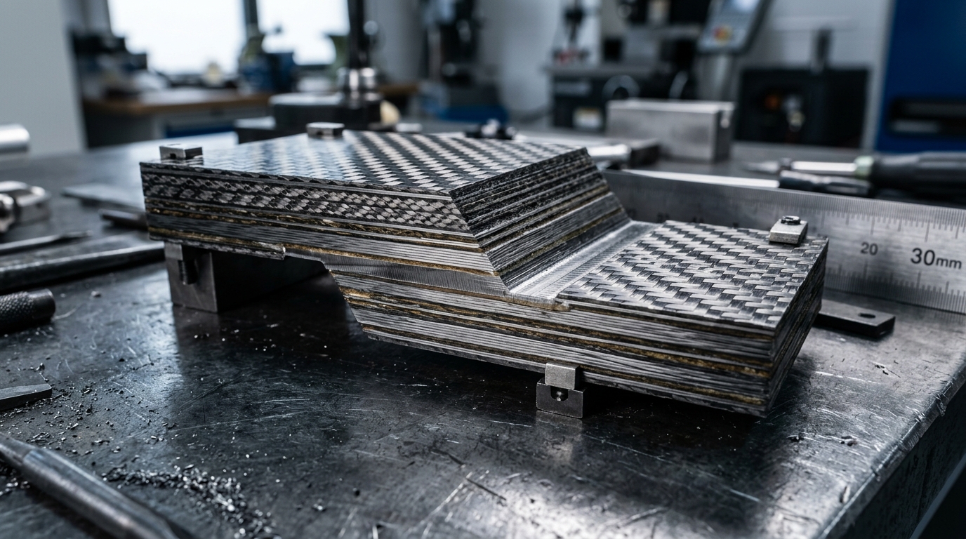
If you want to understand how carbon fiber actually behaves under real-world torture, do not look at a clean CAD model or an idealized finite element simulation.
Look at 3,000 shattered, cracked, crushed, and buckled carbon bicycle frames dragged across a concrete shop floor.
Between 2004 and 2014, operating out of our Santa Monica workshop, Predator Cycling ran an engineering autopsy lab disguised as a composite repair facility. Alongside building more than 1,100 bespoke custom frames from raw pre-preg, we repaired over 3,000 damaged composite bicycles sent to us by amateur racers, bike shops, and professional teams across the country—as documented in our Autodesk University structural overview.
Every broken top tube, cracked chainstay, and delaminated bottom bracket shell told a physical story. It exposed where factory engineers designed for weight on paper, but completely underestimated real-world shear loads, clamp fatigue, and torsional twist.
Here is the engineering forensic breakdown of how composites fail, how structural scarfing actually works, and how cutting into thousands of ruined bikes made us fundamentally better composite manufacturers.
The Santa Monica Crucible: 1,100 Builds, 3,000 Autopsies
In the early 2000s, carbon fiber bicycles were transitioning from exotic curiosity to mass commercial production. The cycling industry was rushing to replace double-butted aluminum and seamless chromoly with carbon composites.
There was just one problem: most bike brands were designing carbon like black aluminum.
They treated anisotropic composite laminates—materials where tensile modulus depends entirely on fiber orientation—as if they were isotropic cast metals. Tubes were laid up with uniform wall thicknesses. Joint transitions were sharp. Resin systems were brittle.
Isotropic Metal (Aluminum/Steel):
  - Equal strength in X, Y, and Z axes.
  - Predictable yielding and plastic deformation before rupture.

Anisotropic Composite (Pre-Preg Carbon):
  - Longitudinal fiber strength: ~3,500 - 4,800 MPa.
  - Transverse matrix strength: ~50 - 80 MPa.
  - Zero plastic deformation: perfectly elastic until brittle failure.
When an aluminum frame takes an impact, it dents. The rider sees the dent and stops riding. When a carbon frame takes an impact, the epoxy matrix micro-fractures inside the laminate while the cosmetic clearcoat often remains pristine. Three weeks later, sprinting out of a corner at 1,200 watts, the tube snaps under catastrophic shear load.
In our Santa Monica shop, we had to solve that problem from first principles. When SoCalCycling ran a technical feature on our workshop in 2012, we were already operating at industrial capacity: tearing down broken structures, inspecting fiber bundles under magnification, and reconstructing load paths.
Forensic Classification: How Carbon Actually Breaks
Out of 3,000 damaged frames inspected, failures were never random. They fell into five distinct structural categories.
| Failure Mechanism | Root Engineering Cause | Visible vs. Sub-Surface | Primary Load Vector |
|---|---|---|---|
| Inter-Laminar Delamination | Inter-ply shear exceeding matrix resin bond strength | Sub-surface void; clearcoat intact | Bending moment / out-of-plane shear |
| Matrix Micro-Cracking | Cyclic fatigue exceeding tensile elongation of cured epoxy | Microscopic web cracks along resin pockets | High-frequency road vibration / torsional chatter |
| Compressive Tube Buckling | Thin tube wall radius-to-thickness ratio () | Sharp transverse crease or complete fracture | Direct axial impact (e.g. front-end crash) |
| Clamp Crush & Hoop Strain | Over-torqued front derailleurs, seatposts, or work stands | Localized resin pulverization; fiber breakage | Radial compressive hoop stress |
| Galvanic Corrosion / Debonding | Bare aluminum inserts touching carbon without dielectric barrier | White galvanic powder; complete joint slippage | Chemical galvanic cell + moisture |
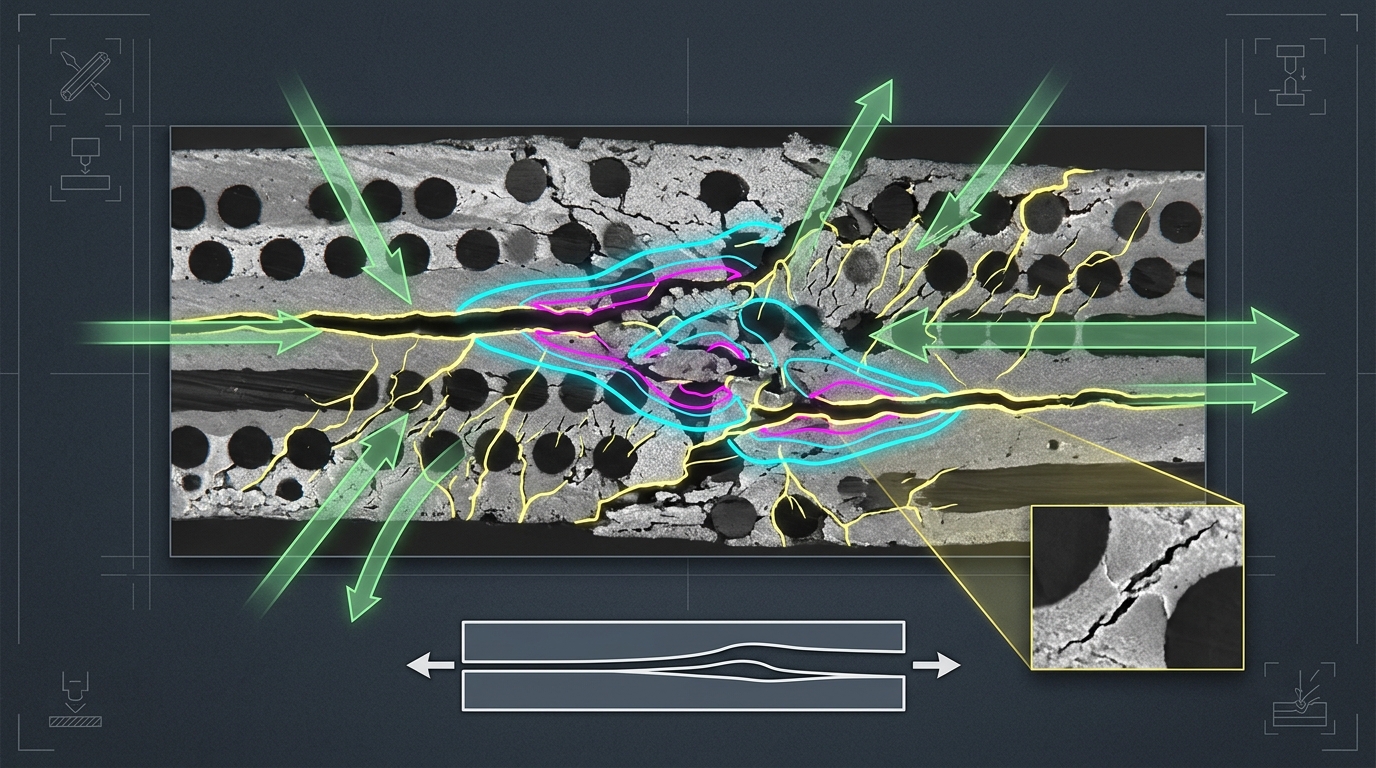
1. The Clamp Crush Epidemic
The most common failure we saw had nothing to do with racing crashes. It was mechanics using standard hex wrenches on front derailleur clamps or seat collars without a calibrated torque wrench.
A bicycle tube is an engineered pressure vessel. It has immense longitudinal tensile capacity, but very little radial hoop stiffness unless you specifically clock plies at and . When a mechanic cranks a steel bolt to 8 Nm on a tube rated for 4 Nm, the clamp crushes the matrix resin. The fibers underneath buckle locally. Once those load paths kink, the tube loses 70% of its buckling strength.
2. High-Shear Delamination
The second most common failure was localized impact delamination. A rock strikes a down tube at 35 mph. On the surface, the rider sees a faint pebble chip in the paint.
Internally, the transverse shockwave travels through the laminate stack. Because cured epoxy has significantly lower shear modulus than the carbon fibers, the resin fractures between plies. The plies separate. Under pedaling loads, the decoupled plies can no longer share bending moments, leading to progressive buckling.
Non-Destructive Inspection: Finding Invisible Fractures
Before touching sandpaper to carbon, you need to know exactly how far the structural damage extends. In aerospace, engineers use phased-array ultrasonic testing. In a boutique shop, we developed a fast, reliable three-stage inspection protocol:
Stage 1: The Acoustic Coin Tap (Resonance Mapping)
It sounds primitive, but acoustic tap testing is rooted in physical vibrational harmonics.
- A solid, fully consolidated composite laminate yields a crisp, high-frequency, metallic resonance.
- As you tap across a delamination zone or void, the frequency immediately deadens into a hollow, dull thud.
- We mapped the perimeter of the void using a wax pencil, marking the true structural boundary.
Stage 2: Deflection and Torsional Loading
We mounted the bare frame on a rigid surface plate, locking the bottom bracket shell and dropouts in precision ground aluminum fixtures. By applying measured static bending loads (20–40 kgf) via dial indicators reading to 0.01 mm, we watched for non-linear deflection anomalies across opposing tube pairs. If the left chainstay deflected 0.4 mm more than the right under identical torque, internal delamination was confirmed.
Stage 3: Low-Viscosity Fluorescent Dye Penetrant
For suspect hairline fractures, we washed the prepped surface with low-viscosity dye penetrant. Under UV blacklight, the capillary action of the dye illuminated micro-fractures extending along fiber bundles that were completely invisible to the naked human eye.
The Math of the Scarf Joint: Why 20:1 to 30:1 Taper Ratios Matter
You cannot “patch” carbon fiber by slapping a wet piece of carbon over a crack. If you do that, you create a massive stress concentration at the edges of the patch. The tube will simply snap right at the boundary of the repair during the next hard sprint.
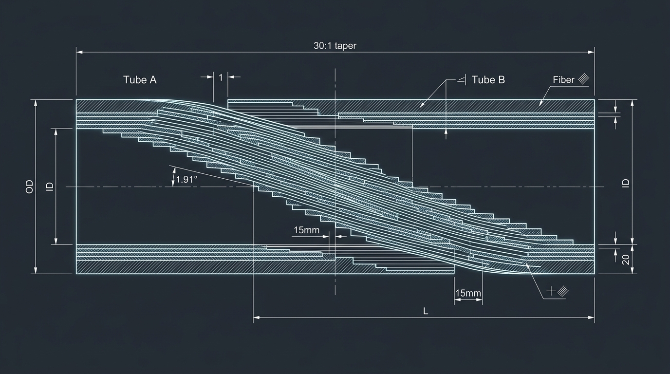
To restore 100% of the original tube’s structural integrity, you must execute a stepped or tapered scarf joint.
The Physics of Taper Ratios
The scarf ratio is the ratio between the taper length () and the laminate wall thickness ():
If a carbon chainstay has a wall thickness of 1.2 mm:
- A 10:1 ratio gives you only a 12 mm taper. The shear stress on the adhesive bond line is too high (), leading to glue line failure.
- A 20:1 ratio gives you a 24 mm taper, distributing shear stress across double the bonding area.
- A 30:1 ratio yields a 36 mm gradual taper (a shallow angle).
At 30:1, the shear stress along the joint drops below the shear strength of the epoxy matrix (). The tensile load transfers smoothly from parent laminate to replacement plies through pure inter-laminar shear.
Parent Tube (Wall thickness = 1.2mm)
═══════════════════════════╲  <-- 30:1 Scarf Taper (36mm long)
Ply 4: Unidirectional 0°   │╲
Ply 3: High-Modulus 45°    │ ╲  Step 3 (12mm)
Ply 2: High-Modulus -45°   │  ╲  Step 2 (24mm)
Ply 1: 3K Twill 0/90°      │   ╲  Step 1 (36mm)
───────────────────────────┴────┴────────────────────────
                             ▲
              Replacement Plies Laid Up In Exact
              Reverse Sequence to Mirror Original Schedule
Matching Modulus and Fiber Orientation
You can’t just throw standard Toray T300 carbon into an ultra-high-modulus M40J frame.
- If you insert lower-modulus fiber, the repair flexes excessively, transferring the load back into the parent laminate and initiating fatigue cracks at the taper edge.
- If you insert higher-modulus fiber, the repair becomes a rigid hard spot that prevents natural frame compliance.
Every single layer removed during the scarfing process was logged: fiber type (unidirectional vs. 3K twill fabric), fiber areal weight (FAW, typically 150–200 g/m²), and ply angle (). The replacement layup mirrored that exact schedule ply-by-ply.
Compaction Dynamics: Debulking, Heat Shrink, and Cure Cycles
Placing the carbon is only half the battle. If your consolidation pressure is poor, your repair will end up with 10% void content and fail within 500 miles.
In our workshop, we utilized two primary compaction methodologies depending on tube geometry:
1. Multi-Stage Vacuum Debulking
For complex shapes like bottom bracket junctions and head tube clusters, we pulled full vacuum (-28 inHg / -0.95 bar) inside custom high-temperature nylon vacuum bags.
- Vacuum debulking removes trapped volatile gases.
- It drives excess resin into perforated release films and bleeder cloth.
- It achieves fiber volume fractions () exceeding 58% to 62%, matching aerospace pre-preg factory standards.
2. High-Tension Heat Shrink Compaction
For straight tubular sections like top tubes, seatstays, and chainstays, we utilized specialized BOPP (biaxially-oriented polypropylene) and polyester shrink tape wrapped under high manual tension (50+ lbs of tension per wrap).
When baked in our convection ovens at ():
- The shrink tape contracts by 12% to 15%.
- This contraction generates localized hydrostatic radial pressures exceeding 100 to 120 PSI.
- The pressure squeezes out every microscopic air void and produces a surface consolidation so tight that it requires minimal finish sanding before paint.
The Circular Economy Before It Was Cool
Years before “circular composite recycling” became an enterprise sustainability buzzword, our Santa Monica shop ran on an active circular economy.
Whenever a high-end European carbon frame was written off as an insurance total loss (for instance, a cracked drop-out on an otherwise immaculate frame), we didn’t throw it in a dumpster.
Total Loss Frame -> Inspection -> Sectioning on Diamond Wet Saw
       │
       ├─► Undamaged Down Tubes: Cut into structural internal backing mandrels
       ├─► Undamaged Stays: Harvested for pre-preg ply testing & burnout tests
       └─► Bottom Bracket Shells: Destructive torsion benchmarks on hydraulic press
We cut undamaged sections on a diamond wet saw to create custom structural donor mandrels. When repairing a crushed seatstay, we could slide a precision-ground, donor carbon sleeve internally, bond it in place under expansion pressure, and scarf the outer repair over the top. The repaired tube was literally stronger and more fatigue-resistant than the day it left the assembly line.
Translating Forensics to Production: Layup Schedules and BB Torsion
The real value of repairing 3,000 frames wasn’t the repair revenue—it was the unfiltered failure database. It became the engineering blueprint for how we designed our own custom frames at Predator Cycling, and later how we architected the 5D Manufacturing Methodology.
Here are the direct design rules we incorporated into our bespoke builds:
1. Continuous Fiber Routing Across Critical Junctions
Most commercial manufacturers mold front triangles and rear triangles separately, then bond them together with stub joints. We saw dozens of rear stays snap clean off the bottom bracket shell due to adhesive shear fatigue.
On our frames, we engineered continuous fiber routing. Unidirectional plies started at the head tube, wrapped continuous through the bottom bracket shell, and ran all the way to the rear dropouts without a single mechanical break in the fiber path.
2. Torsional Bottom Bracket Redundancy
The bottom bracket shell experiences violent out-of-plane torsional shear every time an 85 kg sprinter steps out of the saddle at 1,400 watts.
When standards like PF30 and BB386 hit the market, commercial frames started cracking around the shell because brands used paper-thin carbon sleeves to shave 30 grams.
We engineered our bottom bracket clusters with:
- Internal multi-axial quadraxial fabric wraps to lock torsional deflection under 0.2 mm.
- Dedicated hoop plies to eliminate bearing bore ovalization.
- Machined aluminum or titanium hardpoints isolated with a non-conductive fiberglass veil to eliminate galvanic corrosion forever.
KEY INSIGHT: When you spend ten years cutting open frames that broke in the field, you stop caring about marketing claims of “featherweight frames.” You realize that 50 grams of extra carbon placed in the correct fiber orientation is the difference between a podium sprint and an ambulance ride.
Summary: Key Engineering Takeaways
- Carbon fiber is not black aluminum: Treating anisotropic composite laminates like isotropic cast metal leads to catastrophic brittle shear failures.
- Scarfing geometry dictates joint survival: Structural composite repair demands a 20:1 to 30:1 taper ratio ( to angle) to drop adhesive shear stress below the epoxy matrix threshold.
- Consolidation is everything: Without proper vacuum debulking or high-tension heat shrink compaction (100+ PSI), void content spikes, ruining fatigue endurance.
- Inspect with physics, not guesswork: Combining acoustic resonance mapping, static deflection measurement, and fluorescent dye penetration catches fractures long before catastrophic failure.
- Feedback drives production: The failure points discovered during 3,000 repairs directly governed our continuous-fiber layup schedules, eliminated bond-line fatigue, and formed the backbone of our custom manufacturing philosophy.
Technical Q&A
Q1: Can a repaired carbon frame ever be as strong as an undamaged original?
A: Yes. When executed with a proper 30:1 scarf joint, matched fiber modulus, and identical ply orientation schedules, the repaired joint has greater surface bonding area and higher local compaction than standard bladder-molded factory seams. On destructive tensile and four-point bend tests, properly repaired tubes routinely fail in the virgin parent material, not at the scarf joint.
Q2: Why is carbon fiber repair so expensive compared to welding steel or aluminum?
A: Time and forensic precision. Preparing a 30:1 scarf taper requires 2 to 4 hours of surgical, step-by-step sanding with diamond abrasives to avoid damaging adjacent plies. Replicating the laminate schedule requires stocking multiple pre-preg materials, debulking under vacuum, applying localized cure cycles, and performing non-destructive inspection. It is aerospace composite fabrication performed on a micro-scale.
Q3: What is the most dangerous hidden failure on a modern carbon bike?
A: Clamp crush from over-torqued front derailleurs or seat collars. Because the exterior paint layer can stretch slightly, the rider often sees nothing on the surface while the underlying structural matrix has been crushed into powder. Under heavy out-of-the-saddle climbing torque, the damaged tube can buckle catastrophically without warning.
Next Step: Join the Discussion
The principles of composite forensics, material traceability, and closed-loop quality control are the foundation of modern digital manufacturing.
- Read our foundational framework: The 5D Manufacturing Methodology.
- Explore our engineering ventures and case studies in our Projects Section.
- Connect with Aram Goganian on LinkedIn to discuss advanced composites, digital twin architectures, and automated manufacturing systems.