Parametric Tooling: Merging Generative Surfaces and CNC CAM
How uniting T-Splines, parametric wireframe skeletons, and multi-axis CNC CAM in Autodesk Fusion 360 eliminated the custom composite tooling bottleneck.
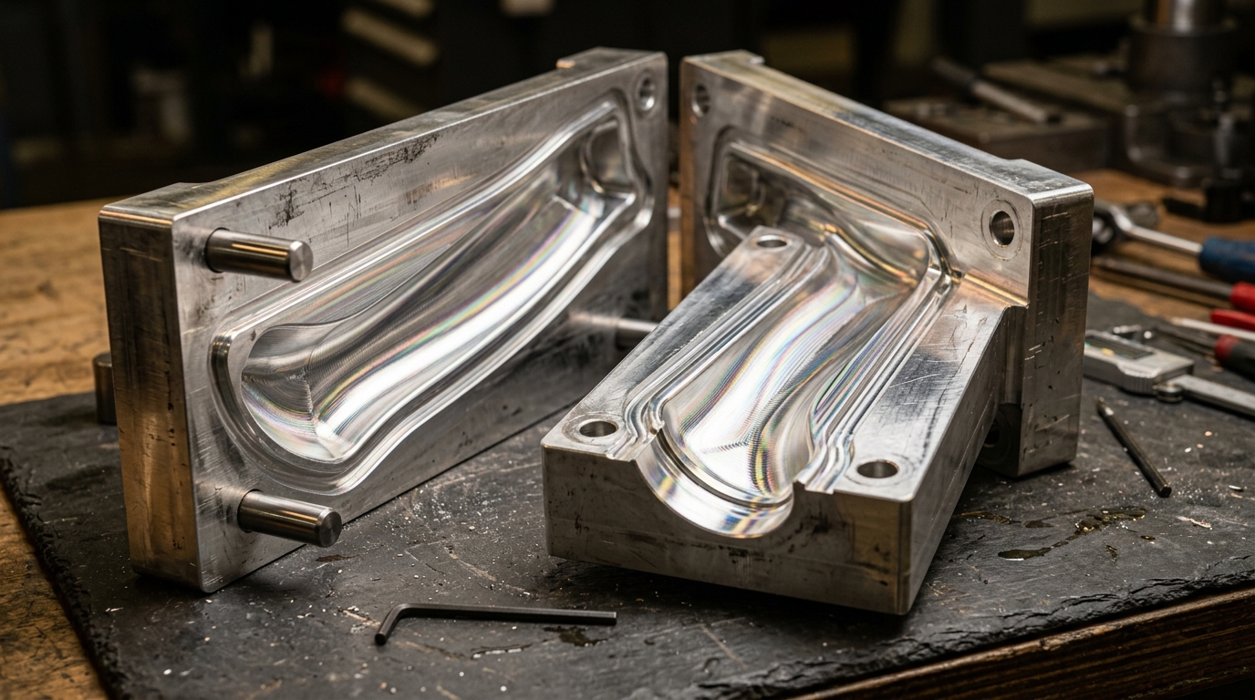
In high-performance carbon composite manufacturing, the single biggest barrier to innovation is not materials science. It is the brutal economics of tooling.
If you want to mass-produce 50,000 identical carbon fiber frames, spending $40,000 to $60,000 per size on hardened tool-steel production molds from overseas suppliers makes economic sense. You amortize the high Non-Recurring Engineering (NRE) tooling cost across tens of thousands of units, wait 16 to 24 weeks for delivery, and pray that your wind-tunnel numbers don’t require an aerodynamic revision.
But if you are building high-mix, custom-tailored aerospace structures, bespoke track bicycles for world-class sprinters, or rapid functional prototypes, traditional offshore tooling models are a death sentence.
When I took the stage at Autodesk University 2018 to deliver our lecture “Framing the Future: Custom Cycling Design in Fusion 360”, our mission at Predator Cycling was to demonstrate a completely integrated digital pipeline.
By unifying organic T-Splines subdivision modeling, parametric wireframe skeletons, and multi-axis CNC CAM inside a single cloud-connected environment, we eliminated file translations, cut mold turnaround times from four months to 48 hours, and brought domestic composite tooling costs down by an order of magnitude.
Here is the engineering methodology of how we bridged parametric geometry, split mold physics, and CNC toolpath generation.
The Custom Tooling Bottleneck: High NRE and Tooling Lock-In
In traditional composite workflows, engineering teams operate in disconnected software silos:
- Industrial Design: An industrial designer sculpts organic tube profiles in a styling tool (like Rhino or Alias), creating “dumb” surface geometry.
- Mechanical CAD: An engineer imports the surfaces via STEP or IGES into SolidWorks or CATIA to shell the interior, add structural hardpoints, and model split molds.
- Machine Shop CAM: The mold geometry is exported again as another neutral file into a third-party CAM package (Mastercam, PowerMill) where a CNC programmer generates machine G-code.
The Fragmented Tooling Pipeline:
[Styling / Rhino] ──(STEP)──► [CAD / SolidWorks] ──(IGES)──► [CAM / Mastercam] ──► [CNC Mill]
        │                             │                              │
        └────── File translation gaps corrupt surface continuity ────┘
The fatal flaw in this fragmented pipeline is geometry amnesia.
Neutral file formats like STEP strip out parametric history. If wind-tunnel aerodynamic data requires extending frame reach by 8 mm or increasing head tube rake by , the entire chain breaks. The mechanical engineer has to manually redraw surfaces, the mold model has to be rebuilt, and the CAM programmer has to re-select hundreds of toolpath drive boundaries from scratch.
That friction traps engineering teams in tooling lock-in. You settle for a suboptimal physical design simply because modifying the tooling CAD is too expensive.
The Parametric Skeleton: Anchoring Organic T-Splines
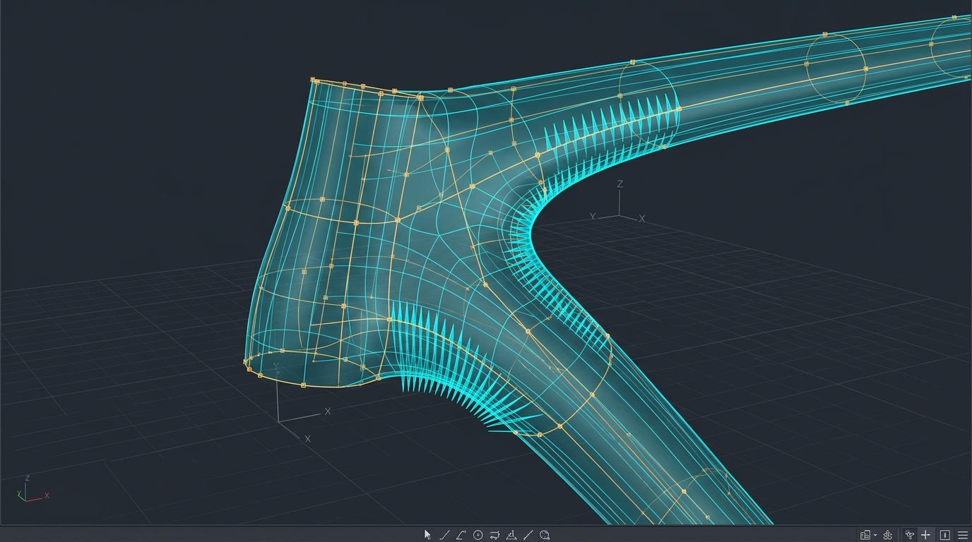
To solve this, we decoupled the geometric hierarchy. Instead of modeling solid shapes directly, we established a master parametric wireframe skeleton.
1. The Wireframe Master
The skeleton is a set of fully constrained 2D and 3D sketch lines driven by global parameters:
StackandReach(rider posture envelope)HeadTube_AngleandSeatTube_AngleBottomBracket_DropandChainstay_LengthTire_Clearance_Radius
2. T-Splines Subdivision Modeling
Over this rigid wireframe skeleton, we sculpted aerodynamic tube junctions using T-Splines (subdivision surface modeling). Unlike standard NURBS surfaces that require complex trimming boundaries and multi-patch stitching, T-Splines allow you to model continuous, organic single-surface topologies with local refinement.
By constraining key T-Spline control vertices directly to the underlying parametric skeleton points:
- When a designer updates
Reachfrom 395 mm to 405 mm in the global parameter table, the skeleton stretches. - The T-Spline control cage moves dynamically with the skeleton.
- The organic head tube and down tube aerodynamic fairing updates automatically while preserving mathematical curvature continuity ( / ).
Surface Continuity Hierarchy:
- G0 (Positional): Surfaces touch, but form a sharp crease (e.g. chamfer).
- G1 (Tangency): Surfaces share common tangent vector; smooth to touch, but abrupt reflection break.
- G2 (Curvature Continuous): Rate of curvature change is continuous; reflections flow seamlessly.
- G3 (Torsion Continuous): Acceleration of curvature change is continuous; aerospace aerodynamic class.
Maintaining continuity across tube intersections isn’t just about cosmetic beauty—it is vital for carbon fiber layup. Sharp or transitional creases create resin-rich zones and stress concentrations where pre-preg carbon plies bridge during compaction, causing localized dry spots and structural failure.
Split Mold Engineering: Parting Lines, Draft Angles, and Flash Gutters
Once the parametric frame body is finalized, we convert the T-Spline surface into a B-Rep (Boundary Representation) solid body. We then perform a boolean subtract operation against raw billet aluminum stock blocks to generate our two-piece or three-piece clamshell split molds.
Tooling for pre-preg carbon composites must obey strict physical rules:
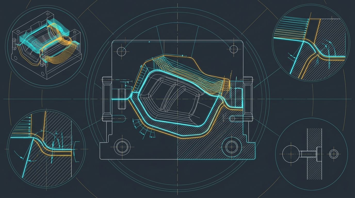
1. Determining the Parting Line
The parting line is the planar or 3D curved boundary where the mold halves meet.
- It must sit at the exact maximum silhouette projection of the part.
- If the parting line is placed even 0.2 mm off the maximum silhouette, you introduce an undercut ( or negative draft).
- When you attempt to demold the cured carbon part after a bake, the part mechanical-locks inside the aluminum cavity. Forcing it out delaminates the composite and destroys the mold surface.
2. Mandatory Draft Angles
We enforce a minimum draft angle of to along all vertical cavity walls. As the cured carbon cools, the aluminum mold contracts slightly more than the carbon (Aluminum CTE vs. Carbon Fiber CTE ).
- While this CTE mismatch allows internal mandrels to pull away, it causes external mold cavities to clamp down slightly on the part.
- A positive draft angle ensures that the moment the mold halves open by 1 mm, the entire surface boundary separates simultaneously without dragging along the cured epoxy clearcoat.
3. Precision Alignment and Flash Gutters
- Hardened Tool-Steel Dowel Pins: Standard mold bolts have clearance tolerances that allow halves to shift by 0.1 to 0.3 mm. We press-fit precision ground hardened tool-steel dowel pins () into reamed holes on the mold flange, locking cavity alignment to within ().
- Resin Flash Relief Gutters: When pre-preg plies are compacted under 100 PSI of internal pressure, excess matrix resin liquefies and flows toward the parting line. We machine a dedicated relief trough (0.5 mm deep, 10 mm wide) 2 mm back from the cavity edge. This gutter captures excess resin squeeze-out without letting hydraulic pressure build up at the seam, preventing thick parting-line witness marks.
Integrated CAM: Direct Toolpaths Without File Translation
Because CAD and CAM share the exact same geometric database in Autodesk Fusion 360, toolpaths are not tied to static imported surfaces—they are tied to the live parametric model.
If the frame geometry updates, we simply right-click the CAM setup and click Generate. The toolpaths recalculate automatically against the new cavity topology.
Integrated Machining Workflow:
[Parametric Solid Mold]
       │
       ├─► 1. 3D Adaptive Clearing (Bulk hogging with 0.500" 3-flute carbide end mill)
       ├─► 2. 3D Semi-Finish Rest Machining (Stepped cleanup with 0.250" ball mill)
       └─► 3. 3D Scallop & Pencil Finishing (0.125" ball mill at 0.004" stepover)
               │
               ▼
   [Sub-16 Micro-Inch RMS Finish (Zero Hand Sanding)]
High-Speed Machining Strategies in 6061-T6 Aluminum
We machine our molds in-house on high-speed CNC milling centers from solid blocks of 6061-T6 aerospace aluminum billet:
-
Adaptive Clearing: Instead of traditional constant-stepover roughing that shocks the tool during cornering, adaptive clearing maintains a constant tool engagement angle (typically to ). We cut at full flute depth (up to ) at high feed rates (180 to 250 IPM), removing 85% of cavity bulk material in under 45 minutes without breaking end mills.
-
Scallop & Pencil Finishing: To eliminate tedious manual polishing that distorts mold accuracy, we program 3D scallop toolpaths using solid carbide ball-end mills running at 12,000 to 18,000 RPM. By keeping the cusp height under 0.0001” (stepover ), the machined aluminum achieves a near-mirror surface finish ( RMS).
The finished mold moves directly from the CNC vise to the composite layup cleanroom—zero sandpaper required.
Internal Bladder Compaction: Aerospace Density Without an Autoclave
Having precision aluminum molds is only half the equation; the composite laminate must be consolidated under intense pressure to eliminate voids.
In aerospace defense programs, parts are cured inside massive multi-million-dollar pressurized autoclaves operating at 90 to 120 PSI. For a high-mix agile manufacturing facility, an autoclave is a massive capital and energy bottleneck.
We developed an internal elastomeric bladder compaction protocol:
Split Mold Compaction Cross-Section:
┌────────────────────────────────────────────────────────┐
│ Upper Mold Half (6061 CNC Machined Aluminum Billet)    │
│  ┌──────────────────────────────────────────────────┐  │
│  │ Pre-Preg Carbon Fiber Layup Stack (0° / ±45° / 90°)│  │
│  │  ┌────────────────────────────────────────────┐  │  │
│  │  │ Internal High-Temp Silicone / Latex Bladder │  │  │
│  │  │ [ Pressurized to 100 - 120 PSI Nitrogen ]  │  │  │
│  │  └────────────────────────────────────────────┘  │  │
│  └──────────────────────────────────────────────────┘  │
│ Lower Mold Half (6061 CNC Machined Aluminum Billet)    │
└────────────────────────────────────────────────────────┘- Tailored Inflatable Bladders: We fabricate custom internal bladders from high-elongation latex or vulcanized silicone that mirror the internal geometry of the tube.
- Layup Application: Pre-preg unidirectional and twill carbon plies are wrapped directly around the deflated bladder.
- Cavity Closure: The bladder and carbon assembly are loaded into the aluminum split mold, alignment dowels engaged, and high-tensile steel cap screws torqued to spec.
- Thermal and Pressure Cycle: The sealed mold is placed inside a convection curing oven. As temperature ramps at to (), the internal bladder is pressurized to 100 to 120 PSI with dry nitrogen.
The expanding internal bladder drives the pre-preg plies against the rigid, precision-machined aluminum cavity walls. Air pockets and volatile gases are forced through the micro-seams into the flash relief gutters.
The resulting consolidated composite part exhibits void contents below 0.8% and fiber volume fractions exceeding 60%—matching autoclave performance at a tiny fraction of the operational cost.
Economics of Tooling: Offshore Steel vs. Domestic CNC Billet
When evaluating manufacturing methods for new products, engineering leaders must balance capital expenditure against speed to market.
| Parameter | Offshore Hard Steel Tooling | Domestic CNC Aluminum Split Molds | 3D-Printed Sacrificial Tooling |
|---|---|---|---|
| Initial NRE Cost (per size) | $35,000 – $60,000 | $3,500 – $6,500 | $800 – $1,500 |
| Lead Time to First Part | 16 to 24 weeks | 2 to 4 days | 24 to 48 hours |
| Design Revision Agility | Near zero (requires mold EDM rework) | Instant (update CAD & re-run CAM) | Instant (re-slice & re-print) |
| Tool Fatigue Life | cycles | 1,500 to 3,000 cycles | Single-use (washout / meltout) |
| Surface Finish Quality | Class-A Mirror Polished | Sub-16 RMS (Direct from Mill) | Layer-line print witness marks |
| Optimal Production Volume | High-volume ( units) | Boutique / High-Mix (10 – 1,000 units) | One-off bespoke prototyping () |
By keeping tooling design and CNC machining in-house with parametric software, we shifted our economics entirely. We could test three radical aerodynamic fork profiles in physical carbon fiber in the time it took an offshore tooling vendor to respond to an initial quotation RFQ.
Summary: Core Engineering Lessons
- Break the software silos: Fragmenting industrial design, mechanical CAD, and CNC CAM across different software vendors introduces geometric translation corruption that destroys agility.
- Anchor organic surfaces to parametric skeletons: T-Splines subdivision modeling allows complex aerodynamic shapes to update dynamically when global engineering parameters change.
- Preserve curvature continuity: Smooth curvature transitions eliminate resin-rich voids and composite ply bridging during compaction.
- Draft angles and parting lines dictate survival: Split molds demand minimum to draft angles and perimeter flash relief channels to ensure clean demolding and zero parting witness lines.
- Domestic rapid tooling wins in high-mix: In-house 6061 aluminum split molds combined with 120 PSI internal bladder compaction deliver autoclave-grade composite parts in 48 hours at 90% lower upfront cost.
Technical Q&A
Q1: Why use 6061-T6 aluminum instead of high-density tooling board (RenShape) for split molds?
A: Thermal conductivity, durability, and pressure containment. While high-density polyurethane tooling boards are fast to machine, they are thermal insulators that cause uneven curing gradients through thick composite laminates. Furthermore, under repeated 120 PSI internal bladder cycles at , tooling board edges crush and degrade after 15 to 20 parts. 6061-T6 aluminum offers rapid, uniform thermal transfer and lasts for thousands of cure cycles without dimensional deflection.
Q2: How do you prevent pre-preg resin from permanently bonding to the raw aluminum mold cavity?
A: A rigorous chemical semi-permanent release agent protocol. The freshly machined aluminum cavity is cleaned with solvent to remove cutting fluids, conditioned with a polymeric mold sealer to fill microscopic metal porosity, and coated with 4 to 5 coats of high-temperature semi-permanent release agent (like Frekote 700-NC). When properly baked and cured, the composite part demolds with minimal friction, leaving zero residue on the metal.
Q3: What happens if a designer models an undercut on a split mold?
A: Mechanical lock. Even an undercut as small as 0.2 mm will prevent the carbon part from exiting the cavity. If forced, the part will delaminate internally, or the tool-steel pry bars will gouge the precision aluminum parting line. When undercuts are physically unavoidable due to complex part geometry, we engineer three-piece or four-piece sliding-core clamshell molds with angled mechanical lifters.
Next Step: Connect and Discuss
Agile product design and domestic manufacturing rely on removing the friction between software geometry and physical tooling.
- Read our foundational framework: The 5D Manufacturing Methodology.
- Explore our engineering case studies in Projects & Ventures.
- Connect with Aram Goganian on LinkedIn to discuss parametric CAD, multi-axis CAM, composite tooling, and agile digital fabrication.