Predators Behind Bars: Fusing 3D-Printed Skeletons with Carbon Aerobars
How I fused load-bearing 3D-printed internal skeletons with directional carbon wraps and rider CFD to eliminate steering slop on $1,795 custom aerobars.
On this page8 sectionsExpandCollapse
In a time trial, the clock is never the real opponent. The air is.
Spend two hours fighting a headwind at 30 mph, and the physics of fluid dynamics becomes brutal. Aerodynamic drag does not scale linearly with speed—it climbs with the square of velocity. Pushing from 20 mph to 30 mph only increases forward speed by 1.5x, yet aerodynamic wind resistance jumps by 2.2x.
When drag dominates over 85% of total resistive power, equipment tolerances stop being cosmetic. Every exposed M5 bolt head, every millimeter of gap between a rider’s forearms and their bar extensions, and every micro-degree of clamp compliance costs precious seconds over a race.
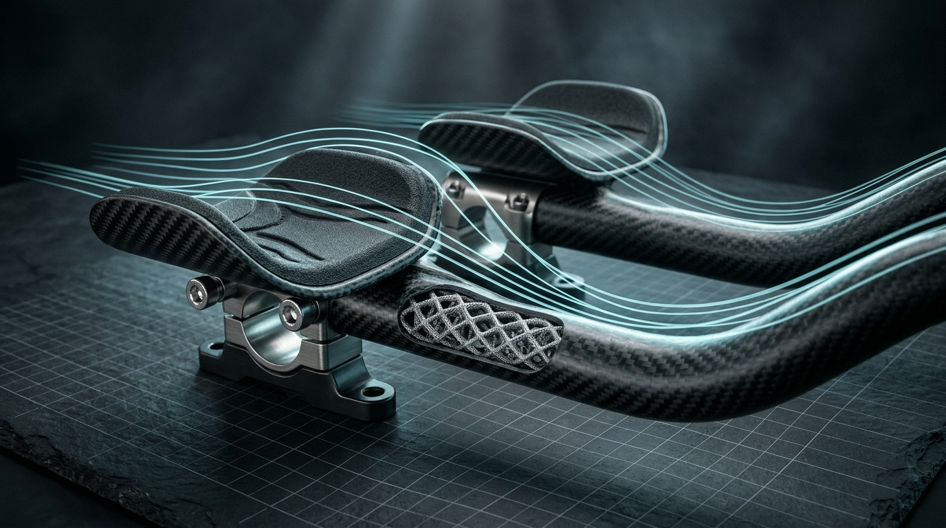
In late 2022, I introduced Predator Cycling’s $1,795 Custom Aerobar Extensions—validated on the road by professional cyclist Cory Williams and profiled in Engineering.com’s feature Predators Behind Bars. Rather than machining heavy aluminum cradles or bolting generic carbon tubes onto an off-the-shelf base bar, I engineered a structural hybrid fusion: an additive 3D-printed internal lattice skeleton co-cured directly into directional carbon fiber wraps.
Why Conventional Bolt-On Aerobars Bleed Watts
Walk down the start ramp at any professional time trial or triathlon, and nearly every bike uses the same compromised mechanical architecture: two cylindrical carbon or aluminum extension tubes clamped onto a base bar via bolted brackets and padded cups.
That bolted architecture introduces two immediate physical failures:
- Steering Slop and Tuck Abandonment: A time-trial bike is inherently tuned for straight-line tracking stability. With narrow bolt-on armrests and round extension tubes, riders experience torsional compliance and forearm lateral slip whenever cornering force rises. Through anything sharper than a gentle sweeper, the rider is forced to break their aerodynamic tuck, sit up, and reach wide for the outer pursuit horns—destroying frontal drag area () just to steer safely.
- Sacrificial Core Deadweight: Even custom-molded one-piece carbon extensions typically rely on polyurethane foam, wax, or wash-out mandrels purely as passive shaping cores. Those cores contribute zero structural load capacity once cured, leaving all bending, clamping, and torsional shear resistance to thick external carbon walls.
Because aerodynamic power scales with the cube of velocity (), holding a compact tuck through a rolling course with frequent corners requires mechanical steering authority without widening the rider’s silhouette.
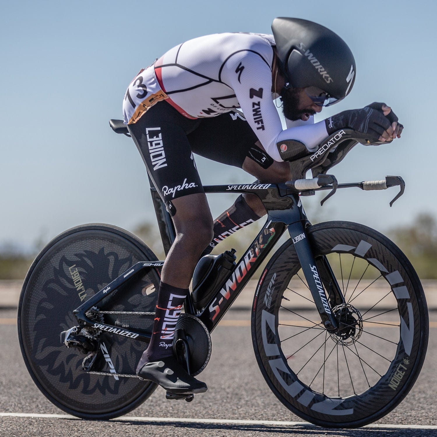
As Cory Williams put it after putting the production extensions under race torque:
“I’ve worked with Aram at Predator Cycling since our early racing days as juniors. The evolution of design presented by Predator is mind-blowing. These extensions, made specifically for my TT position have allowed me to lock-in my upper body posture. They’re stiff, responsive, and give me so much more stability.”
From Photogrammetry to Structural Hybrid Fusion
I first began bringing industrial 3D printing into Predator Cycling’s composite workflow around 2016—initially for tooling masters, fitment checks, and additive prototypes like my 2016 Rio Olympic cockpit integration. By 2022, pairing Autodesk Fusion 360 parametric modeling, Ansys CFD, and local workstation compute on my Lenovo ThinkStation P620 allowed me to turn additive cores into active load-bearing structural components.
As I explained in Engineering.com:
“Unlike other manufacturers utilizing traditional core materials as purely shaping cores, we’re using 3D print material to create internal surfaces and structural hybrid fusions, in which the cores and the external wraps work together to create substantially strengthened and measurable effectiveness for the end users. Imagine a 3D print ‘skeleton’ with the ability to fuse with carbon fiber for structural integrity rather than a traditional wrap of a solid core system.”
Step 1: Anatomical Photogrammetry and Rider CFD
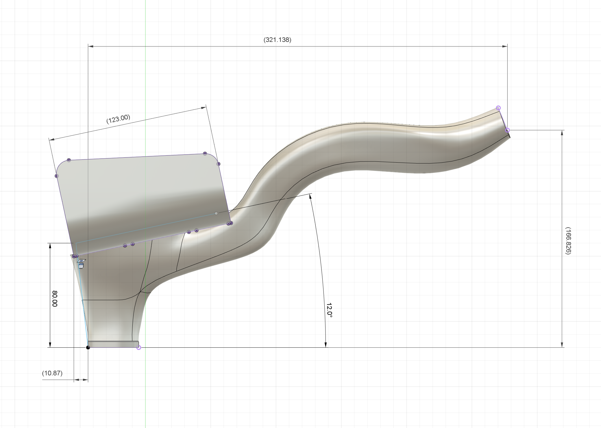
Instead of fitting an athlete to discrete 5 mm spacer increments, I start by digitizing the rider’s actual forearm anatomy and sprint posture using multi-angle photogrammetry and Predator Lab fit coordinates.
- Custom Forearm Cradles: The upper extension surface captures the exact curvature of the athlete’s ulna, wrist transition, and grip angle. Because the cradle wraps snugly around the arm, lateral steering torque transfers directly through bone contact rather than palm tension.
- Linked Base-Bar Geometry: Instead of clamping onto a round bar with exposed M5 hardware, the custom extensions fuse seamlessly into Predator’s airfoil cockpit setup. Removing clamp bosses eliminates flow separation trips directly ahead of the rider’s chest.
- Yaw-Sweep CFD Validation: Before printing a single lattice core, I run computational fluid dynamics across yaw angles to align trailing-edge camber and wrist shrouding with the athlete’s torso boundary layer.
Step 2: Internal Lattice Topology
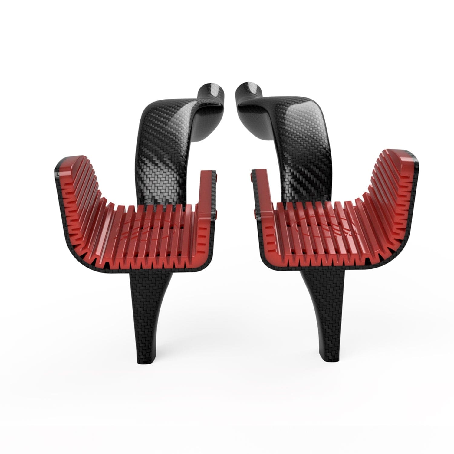
Inside Fusion 360 and generative solver workflows, I synthesize an internal structural skeleton tailored to the exact moment diagram of the forearm cradle. Where a solid foam core merely fills space, an engineered polymer lattice provides:
- Internal Shear Webbing: Continuous internal diagonal ribs connect upper compression walls and lower tension skins, resisting cross-sectional ovalization when the rider pulls hard out of a saddle.
- Mechanical Bond Anchors: Micro-textured lattice surfaces and controlled resin-infusion channels lock the internal core chemically and mechanically to the structural carbon plies during cure.
- High-Mix Customization Without Tooling NRE: Every rider has distinct arm lengths, supination angles, and computer/shifter switch pockets. Printing the internal structural core directly from parametric CAD avoids cutting a dedicated $25,000 aluminum mold for every single athlete.
Directional Carbon Overwrap Mechanics
A hybrid skeleton only works if the exterior carbon fiber layup respects orthotropic mechanics. Carbon fiber carries load exclusively along its fiber axis—unlike isotropic 6061-T6 aluminum.
To balance stiffness, torsional stability, and impact resilience across the fused aerobar assembly, I layer pre-preg plies along three principal structural vectors:
- Longitudinal Bending Plies (): Unidirectional high-tensile carbon aligned along the main axis of the extension to carry cantilever tension on top and compression underneath when the rider drives weight onto the forearms over rough chip-seal roads.
- Torsional Hoop Wraps (): Circumferential plies locking the forearm cradle walls together and preventing splitting around shifter mounts and base-bar junction collars.
- Biaxial Shear Plies (): Cross-oriented woven and unidirectional plies absorbing combined bending-plus-twist cornering loads—exactly the forces generated when a rider carves a technical corner while staying locked inside the aero tuck.
| Architecture Dimension | Bolt-On Commercial Extensions | Traditional Carbon over Foam Core | Predator Structural Hybrid Fusion |
|---|---|---|---|
| Core Function | None (hollow tube + metal clamps) | Passive sacrificial shaping core only | Active load-bearing 3D-printed skeleton |
| Base-Bar Interface | Multi-bolt clamp bracket (exposed hardware) | Bonded collar or bolted cradle | Fused monolithic cockpit transition |
| Cornering Control | High steering slop; forces reach to horns | Moderate stiffness; generic elbow pad cups | Snug anatomical forearm lock; tuck held in turns |
| Custom Fit Cost | Limited to spacer stacks & angle shims | Prohibitive custom billet mold NRE | Parametric photogrammetry -> direct print core ($1,795) |
| Aerodynamic Flow | Tripped by bolts, straps, and clamp gaps | Smooth shell, fixed off-the-shelf profile | Rider-specific CFD forearm-to-chassis shroud |
Grounded in 5D: Bits, Atoms, and Production Traceability
This hybrid workflow sits squarely inside my 5D Manufacturing Methodology and connects directly to the composite production capabilities I commercialize through MACC Composites:
- 01 Design: Photogrammetry scan and parametric wrist/shifter envelope defined in Fusion 360.
- 02 Develop: Rider-coupled CFD drag sweeps and directional laminate structural validation.
- 03 Data Log: Serialized digital birth certificate recording print lattice batch, resin system, and cure profile.
- 04 Drive: Direct-to-printer internal skeleton fabrication followed by directional pre-preg consolidation.
- 05 Deliver: Final trimmed cockpit verified against fit coordinates and shipped ready for competition.
What changed between 2016 and 2022 was not the laws of aerodynamics—it was computational access. Having local workstation acceleration and AI-assisted CAD tooling removed the traditional trade-off between one-off bespoke ergonomics and repeatable structural engineering.
Key Engineering Takeaways
- Solve for cornering aerodynamics, not just wind-tunnel straight lines: An aerobar that forces a rider onto the outer pursuit horns in every shallow bend surrenders massive real-world time regardless of its straight-ahead number.
- Turn cores into structure: Replacing inert foam mandrels with engineered 3D-printed internal skeletons transforms additive manufacturing from a prototyping crutch into an active shear web fused with directional carbon fiber.
- Parametric customization beats fixed mold NRE: For athlete-specific interfaces—from elite sprinters like Cory Williams to specialized medical and EV composite brackets—combining direct digital internal cores with controlled carbon overwraps eliminates custom tooling lock-in.
Engineering Resources
- Engineering.com: Predators Behind Bars — A Story of Bicycle Aerodynamics and Manufacturing (Dec 1, 2022)
- Ergometry, Biomechanics, and the Rio 2016 Olympic Cockpit
- Predator Labs: Computational Cycling & Athlete OS
- MACC Composites: Structural DFM & Materials Commerce
- The 5D Manufacturing Methodology
- Speaking, Courses & Press Archive
- Connect with Aram Goganian (Principal Systems Architect & Engineering Leader) on LinkedIn