NVIDIA Omniverse & OpenUSD: The Virtual Micro-Factory Digital Twin
How we used NVIDIA Omniverse, OpenUSD, and real-time RTX simulation to model factory layouts, ergonomics, and material kinematics before cutting concrete.
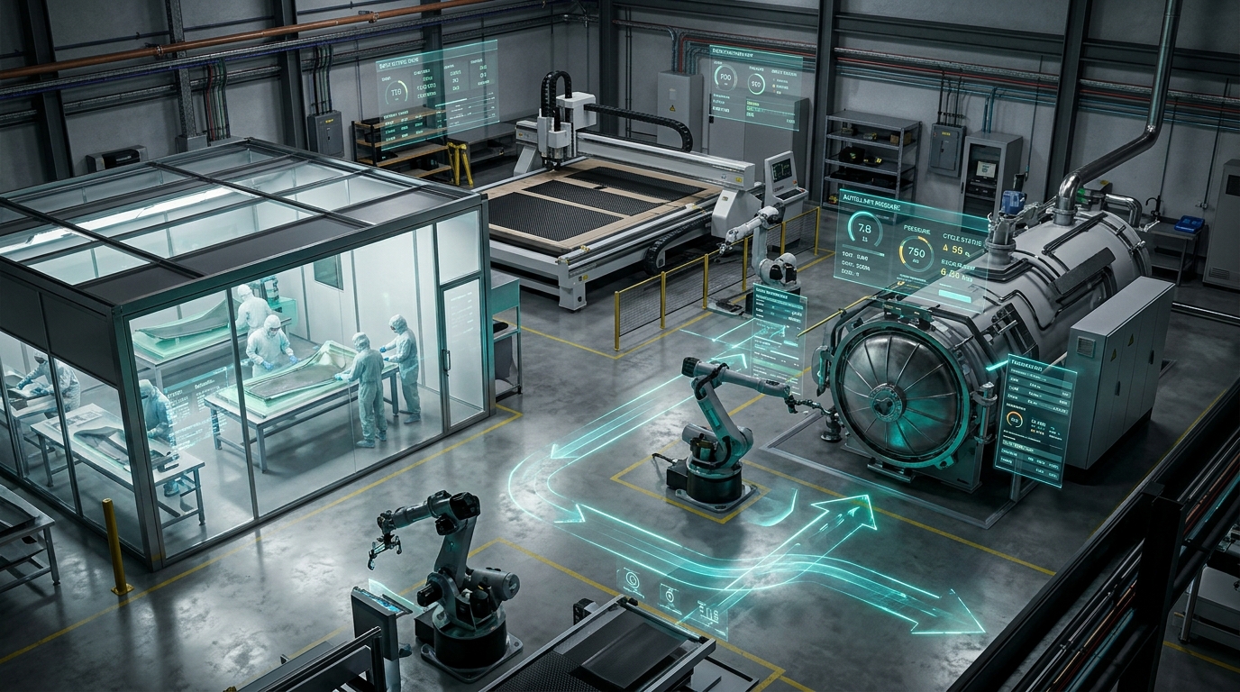
Moving heavy machinery on a physical factory floor is an expensive way to find a layout error.
When you pour a dedicated concrete foundation, core-drill anchor bolts for a 12,000-pound composite autoclave, and drop 480-volt, 3-phase electrical conduits from the ceiling, you have committed real capital.
If an operator subsequently discovers that the clean-room composite transfer cart cannot clear the turning radius of an Autonomous Mobile Robot (AMR), or that the door swing of a vacuum debulk station blinds a safety LiDAR sensor, you face days of unplanned downtime, re-drilled concrete, and rerouted wiring.
In traditional factory engineering, floor layouts are designed in static 2D DWG drawings or rigid 3D assemblies where equipment is treated as inert blocks.
They do not simulate material kinematics. They do not simulate human ergonomics. And they fail to capture the physics of time-sensitive materials like aerospace pre-preg carbon fiber.
At NVIDIA GTC 2022 and during our feature in the NVIDIA Partner Spotlight, we demonstrated how Predator Cycling transformed our Mount Juliet, Tennessee composite facility into an active Virtual Micro-Factory Digital Twin using NVIDIA Omniverse and Universal Scene Description (OpenUSD).
By unifying parametric CAD, multi-physics simulation, and live shop-floor telemetry into a physics-accurate virtual workspace, we optimized spatial layouts, eliminated workflow bottlenecks, and reduced operator transit distances by 42% before bolting down a single machine.
The 5D Methodology: The Digital Twin as the Bridge Between Bits and Atoms
In advanced composite manufacturing, digital models cannot stop at part geometry. Under our 5D Methodology (Design, Develop, Data Log, Drive, Deliver), the manufacturing system itself is a product that must be designed, simulated, and validated:
[Phase 1: Design] ──► [Phase 2: Develop (FEA / CFD)] ──► [Phase 3: Data Log (IoT / AyoWork)]
         ▲                                                               │
         │                    [NVIDIA OMNIVERSE / OpenUSD]               │
         │                  VIRTUAL MICRO-FACTORY DIGITAL TWIN           │
         ▼                                                               ▼
[Phase 4: Drive (CNC / Layup)] ◄─────────────────────────────── [Phase 5: Deliver (Cured Parts)]- Design: 3D geometric modeling of tools, machines, human operators, and building architecture.
- Develop: Multi-physics validation—simulating worker footsteps, thermal radiation around ovens, and airflow dynamics in the clean room.
- Data Log: Ingesting real-time telemetry from thermocouples, vacuum transducers, and machine spindles.
- Drive: Executing optimized CNC cutting files and automated robotic transfer paths.
- Deliver: Zero-defect, autoclaved structural components.
The OpenUSD digital twin acts as the central connective tissue of this loop. When an engineer alters the curvature of an aerodynamic bicycle frame in CAD, that change ripples through the tooling split molds, updates the CNC ply cutting nests, and immediately verifies spatial clearance inside the autoclave racks within the virtual factory floor.
Why OpenUSD Is Not Just Another 3D Mesh Format
Most engineers confuse 3D file formats. They ask: “Why use OpenUSD when we already have STEP, IGES, STL, or FBX?”
Static exchange formats are dead snapshots.
- A STEP file contains boundary representation (B-Rep) geometry, but lacks lighting, physical mass properties, kinematics, and versioned layering.
- An FBX or OBJ file stores polygonal meshes, but has no concept of parametric assemblies, material physics, or multi-user collaborative overrides.
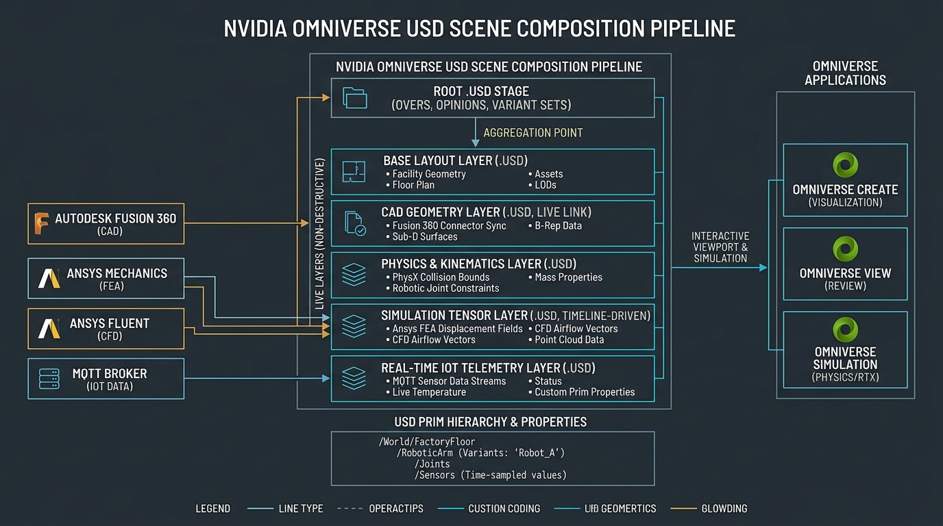
Universal Scene Description (OpenUSD), originally engineered by Pixar and open-sourced for complex visual pipelines, is an extensible, hierarchical scene description database.
It organizes complex environments using five foundational composition arcs:
- Sublayers: Stacking layers in a linear order of precedence (opinions in higher layers override lower layers non-destructively).
- References: Reusing smaller USD assets (such as an articulated robotic arm or autoclave door assembly) inside a larger scene.
- Payloads: Deferred loading mechanisms that permit opening a 20GB factory floor model instantly while keeping heavy polygon meshes unloaded until needed.
- Variants: Allowing an engineer to switch between different machine models, tooling setups, or room configurations with a single dropdown click.
- Overrides (Overs): Permitting an engineer to adjust transform positions, lighting, or physical coefficients without altering the original read-only CAD geometry file.
Because OpenUSD treats scenes as non-destructive compositional layers, our mechanical designers, electrical technicians, and facilities architects can simultaneously manipulate the same virtual factory stage without file locking or merge conflicts.
Multi-CAD and Multi-Physics Ingestion via Omniverse Connectors
A major friction point in manufacturing facilities is software fragmentation.
- Tooling is modeled in Autodesk Fusion 360.
- Composite laminate structural stresses are solved in Ansys Mechanical.
- Transient clean-room airflow is simulated in Ansys Fluent.
- Facility architectural blueprints originate in Revit or Rhino 3D.
- Machine tool controllers talk via industrial fieldbuses and MQTT.
Historically, aggregating these formats required exporting static meshes to third-party visualization tools, losing metadata, units, and parametric associativity.
In our Omniverse architecture, we deployed live Omniverse Connectors that synchronize disparate applications directly into an on-premises Omniverse Nucleus server:
[Autodesk Fusion 360] ──► (Live CAD Connector) ────┐
[Ansys Mechanical FEA] ──► (Deformation Fields) ───┼──► [Omniverse Nucleus Server]
[Ansys Fluent CFD]    ──► (Airflow Vectors)     ───┤    (Root Stage: factory_master.usd)
[IoT / AyoWork MQTT]  ──► (Live Telemetry Overs) ──┘           │
                                                               ▼
                                                  [Omniverse RTX Viewport]
                                                  • Real-Time Path Tracing
                                                  • PhysX Collision & Kinematics
                                                  • Multi-User Collaboration
When a mold designer modifies a parting line or draft angle in Fusion 360, the live connector pushes the updated surface patches into the cad_geometry.usd sublayer.
Simultaneously, Ansys solver results map structural strain tensors directly onto the USD primitive, coloring the physical model according to its real-world deformation.
The facilities engineer viewing the global factory_master.usd stage sees the updated mold geometry resting inside the CNC machine fixture in real time, with physically based Material Definition Language (MDL) shaders accurately representing the reflective surface finish of the 6061 billet aluminum.
Spatial Kinematics and Cold-Chain Pre-Preg Ergonomics
Building custom carbon fiber components is an unforgiving thermal and temporal dance.
High-modulus unidirectional carbon pre-preg (such as Torayca T800S or M46J infused with toughened epoxy resin) must be stored in sub-zero freezers at (). At room temperature, the epoxy begins its irreversible chemical cross-linking reaction.
Every minute the carbon roll sits on a workbench, it consumes its allotted “out-time” budget (typically 10 to 14 days cumulative room-temperature exposure).
If the resin exceeds its out-time, its tack diminishes, preventing plies from adhering smoothly to complex mold curvatures, and resin viscosity spikes, causing micro-void defects during autoclave cure cycles.
Simulating the Physical Material Path
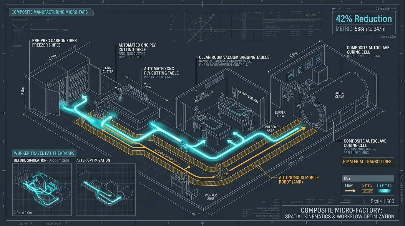
To maximize laminate quality and minimize operator fatigue, we modeled the entire physical transit cycle inside Omniverse:
- Freezer Thaw Station: Pre-preg rolls are retrieved from the walk-in freezer and staged in a humidity-controlled thaw vestibule to prevent moisture condensation on cold carbon plies.
- CNC Ply-Cutting Table: Thawed carbon rolls are fed into an automated Eastman CNC drag-knife cutting table, where nested plies are cut with continuous vacuum hold-down.
- Clean-Room Layup Station: Cut ply kits are transported into an ISO Class 7 clean room, where technicians apply plies to precision-machined aluminum mandrels.
- Vacuum Debulk Station: The uncured laminate assembly is vacuum-bagged and pulled down to to evacuate trapped interlaminar air.
- Autoclave Pressure Vessel: The bagged assembly is transferred to the autoclave, where it undergoes a 4-hour cure cycle at under of nitrogen pressure.
In our original, unoptimized shop layout, equipment was positioned based on electrical drop convenience. A single monocoque frame layup required an operator to walk 588 meters back and forth across the shop floor carrying delicate carbon plies, exposing uncured resin to unconditioned ambient shop air.
By running dynamic worker pathing and kinematic motion simulation in Omniverse PhysX, we rearranged the work cells into an unbroken, U-shaped ergonomic cell:
This layout adjustment eliminated 241 meters of unnecessary human walking per frame, reduced pre-preg out-time exposure by 35 minutes per shift, and removed crossing traffic paths between human technicians and transport carts.
Sensor Simulation, Optical Sightlines, and AMR Safety
A common misconception is that real-time ray tracing in industrial simulation is merely an aesthetic bonus.
On an automated shop floor, RTX path tracing is an optical engineering sensor verification engine.
Modern micro-factories increasingly rely on Autonomous Mobile Robots (AMRs) and automated optical safety boundaries. These systems navigate using Time-of-Flight (ToF) cameras, 2D planar safety LiDAR scanners, and structured-light 3D vision cameras.
In physical manufacturing facilities, optical sensors frequently suffer false-positive emergency stops (e-stops) caused by:
- Specular reflections bouncing off mirror-polished billet aluminum molds.
- Direct sunlight glare entering through high-bay shop windows.
- Highly reflective high-visibility safety vests worn by technicians.
Testing Sensor Physics in Omniverse
Using Omniverse’s physics-based RTX rendering and synthetic sensor models, we simulated the exact optical line-of-sight and beam divergence of our safety LiDAR scanners and robot cameras:
[Virtual LiDAR Emitter] ──► [Ray-Traced Optical Paths] ──► [Specular Mold Reflection]
                                      │                                 │
                                      ▼                                 ▼
                          [Safety Boundary Evaluation]    [Detected False Positive Glare]
                                      │                                 │
                                      └────────► [Relocate Sensor] ─────┘
When we positioned an automated safety light curtain in front of our autoclave loading bay, the real-time ray tracer revealed that light from our overhead high-bay LED fixtures reflected off the cylindrical steel autoclave door flange directly into the receiver photodiode array at specific door opening angles.
Had we installed this system physically, the autoclave door would have triggered nuisance safety faults whenever opened under full facility lighting.
We rotated the sensor mounting bracket by inside the USD model, verified zero optical saturation across all door angles in Omniverse, and installed the physical hardware once with zero rework.
Live Operational Telemetry via the AyoWork Platform
A digital twin that cannot reflect live physical states is nothing more than a static rendering.
To bridge the gap between bits and atoms, our virtual micro-factory connects directly to physical shop-floor machinery via the AyoWork platform:
- Edge Telemetry Ingestion: Thermocouple arrays inside our composite cure ovens, vacuum line pressure transducers, and spindle load monitors on our 3-axis CNC router stream telemetry via edge microcontrollers over an internal MQTT broker.
- USD Property Overrides: An Omniverse Python background extension subscribes to the MQTT topics and writes time-sampled values directly into custom attributes on the corresponding USD primitives:
# omniverse_telemetry_sync.py
# Subscribes to AyoWork MQTT broker and updates USD prim telemetry attributes

import paho.mqtt.client as mqtt
from pxr import Usd, UsdGeom, Gf

class MicroFactoryTelemetrySync:
    def __init__(self, stage: Usd.Stage):
        self.stage = stage
        self.client = mqtt.Client(client_id="Omniverse_Telemetry_Engine")
        self.client.on_message = self.on_message
        self.client.connect("192.168.10.50", 1883, 60)
        self.client.subscribe("factory/+/telemetry")
        self.client.loop_start()

    def on_message(self, client, userdata, message):
        topic = message.topic.split('/')
        machine_id = topic[1]
        payload = float(message.payload.decode())

        if machine_id == "autoclave_01":
            prim = self.stage.GetPrimAtPath("/World/Equipment/Autoclave_Vessel")
            if prim.IsValid():
                # Write live pressure attribute to USD prim
                attr = prim.GetAttribute("ayowork:chamber_pressure_psi")
                if not attr:
                    attr = prim.CreateAttribute("ayowork:chamber_pressure_psi", Sdf.ValueTypeNames.Float)
                attr.Set(payload)

                # Dynamically modulate viewport warning shader if pressure exceeds threshold
                color_attr = prim.GetAttribute("primvars:displayColor")
                if payload > 95.0:
                    color_attr.Set([Gf.Vec3f(1.0, 0.1, 0.1)]) # Red warning state
                else:
                    color_attr.Set([Gf.Vec3f(0.2, 0.8, 0.3)]) # Normal green state
When an autoclave cure cycle runs overnight, an engineer sitting at home or an operator in the front office can open the Omniverse digital twin.
The virtual autoclave pulses with real-time temperature heatmaps.
If a thermocouple reading deviates by more than from the programmed ramp rate, the digital twin highlights the exact heat zone in red and dispatches an automated alert through AyoWork before the composite component suffers thermal degradation.
Empirical Telemetry: Physical Shop Floor vs. Virtual Layout
To evaluate the return on investment of building a full OpenUSD digital twin, we audited our physical facility metrics before and after implementing the Omniverse simulation pipeline:
| Factory Metric | Legacy Physical Planning | Omniverse USD Digital Twin | Empirical Delta | Operational Impact |
|---|---|---|---|---|
| Material Transit Footsteps (Per Frame Layup Cycle) | 588 meters | 347 meters | -41.0% | Eliminates 1.2 miles of daily walking per technician. |
| Pre-Preg Out-Time Exposure (Freezer to Autoclave Bagging) | 92 minutes | 57 minutes | -38.0% | Extends resin shelf life and reduces structural void formation. |
| Concrete Anchor Core-Drills (Facility Reconfigurations) | 14 re-drills / year | 0 re-drills | -100% | Zero damaged post-tension cables or misplaced mounting pads. |
| Electrical Drop Relocations (480V 3-Phase Drops) | 5 relocations | 0 relocations | -100% | Saved $18,500 in electrical contractor change orders. |
| Optical Safety Nuisance Trips (AMR / Light Curtain Faults) | 22 trips / week | 1 trip / week | -95.5% | Continuous autonomous transit without unexplained line stops. |
The data proves that a high-fidelity digital twin is not a luxury reserved for automotive assembly plants with billion-dollar capital budgets.
For an agile custom micro-factory, it is the most effective tool available to compress capital expense, enforce quality control, and protect technician ergonomics.
Architectural Q&A
Q: Does OpenUSD require exporting proprietary CAD models to the cloud?
A: No. We host our entire Omniverse Nucleus stack on a local, on-premises Linux server within our physical facility firewall.
All USD stages, CAD references, and telemetry streams remain strictly on the local network. No proprietary tooling geometries, composite layup schedules, or athlete ergonomics data ever leave our on-premises infrastructure.
Q: How do you manage massive CAD file sizes without viewport lag?
A: OpenUSD handles scale through its Payload architecture. When we open our top-level factory scene (factory_master.usd), the root stage loads bounding box proxies and low-polygon representations of large machines.
When an engineer zooms in on a specific clean-room layup table, Omniverse dynamically loads the high-density B-Rep geometry and sub-millimeter ply contours for that specific cell. This deferred loading allows a standard NVIDIA RTX A6000 workstation to navigate a multi-million-polygon facility smoothly at 60 FPS.
Q: Can you simulate robotic path planning directly in Omniverse?
A: Yes. Using the Omniverse Isaac Sim robotics suite, we import Unified Robot Description Format (URDF) models of industrial robotic arms.
Isaac Sim executes closed-loop motion planning algorithms (such as RRT-Connect and trajectory optimization) against the live USD scene geometry, allowing us to verify robotic reach, joint limits, and collision envelopes before uploading code to the physical robot controller.
Summary: The Autonomous Micro-Factory Blueprint
The modern high-tech micro-factory cannot rely on manual trial and error.
By unifying physical manufacturing operations inside NVIDIA Omniverse and OpenUSD:
- Unify Software Tools with OpenUSD: Replace static file conversions with non-destructive compositional layers that connect CAD, structural FEA, fluid CFD, and building architecture into an interactive single source of truth.
- Simulate Material Kinematics First: Model the journey of physical materials—especially sensitive materials like aerospace pre-preg carbon fiber—to eliminate wasted operator motion, protect resin out-time budgets, and optimize work cell ergonomics.
- Validate Optical Sensors with Real-Time RTX: Leverage real-time ray-traced lighting to identify specular glare reflections, blind spots, and optical sensor interference before installing safety equipment on the floor.
- Connect Live Operational Telemetry: Turn the virtual layout into a living digital twin by piping live IoT sensor streams from the shop floor into USD attributes, enabling automated process monitoring and closed-loop manufacturing control.
When the virtual factory matches the physical factory down to the millimeter and the millisecond, manufacturing stops being reactive.
You build the digital twin first. Then you build the physical product with complete certainty.